

A voltage-load-sensitivity-based auxiliary control method for static synchronous compensator primary frequency regulation
 0
0 
Abstract
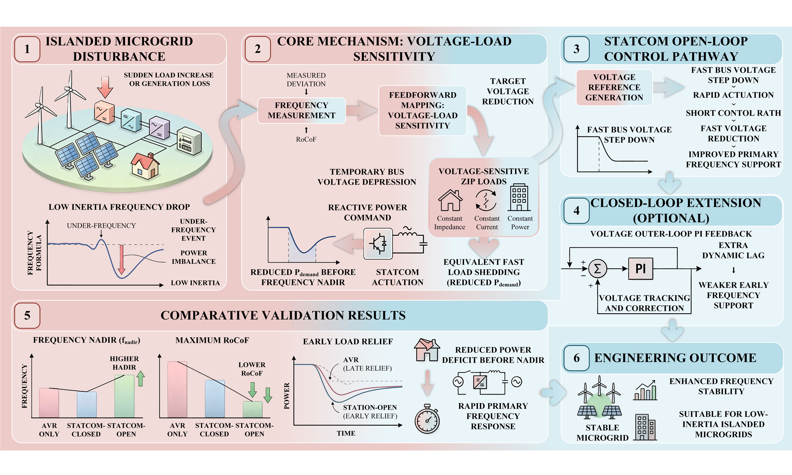
With the increasing penetration of distributed renewable energy and the widespread integration of power electronics, the primary frequency response in islanded microgrids encounters significant challenges. To address this issue, a voltage-load-sensitivity-based auxiliary control method for Static Synchronous Compensator (STATCOM) is proposed, enabling their use in primary frequency regulation. During low-frequency events, the voltage at the controlled node is rapidly reduced, thereby effectively implementing fast load shedding for sensitive loads through Conservation Voltage Reduction (CVR) without direct active power injection. Furthermore, a closed-loop extension that incorporates an additional voltage outer loop is presented to compensate for the early power deficit. Simulation results demonstrate that, compared to traditional Automatic Voltage Regulation (AVR) and the combination of AVR with a STATCOM, the open-loop scheme rapidly lowers the local voltage before the frequency nadir occurs, which indicates a substantial improvement in frequency metrics via load shedding. Due to its earlier actuation timing, shorter response path, and broader control range, the open-loop feedforward control exhibits advantages over the closed-loop system in this scenario.
Keywords
1. INTRODUCTION
With the increasing penetration of distributed renewable energy, power systems exhibit low inertia, strong coupling, and low predictability in topology, inertia, and control patterns[1-4]. After major disturbances, controlled islanding into several isolated microgrids is regarded as critical for enhancing system resilience and recovery, as it contains fault propagation and maintains the power supply to critical loads[5-7].
However, primary frequency control presents greater challenges in islanded microgrids compared to traditional large-scale power grids. First, the high penetration of power electronic devices in microgrids significantly reduces the equivalent inertia, which makes the frequency more sensitive to power imbalances. Consequently, larger frequency nadirs and higher Rates of Change of Frequency (RoCoFs) are often observed[8]. Second, distributed power sources widely adopt external characteristic control based on droop and virtual inertia; the coupling between primary and secondary control levels is complex and constrained by communication delays and data uncertainty[9]. Third, the high R/X ratio inherent to distribution networks leads to more pronounced coupling between voltage and active/reactive power, which may amplify the coordinated risks of frequency and voltage disturbances under dynamic load conditions[10]. Therefore, achieving rapid primary frequency support without significantly increasing energy expenditure and communication overhead remains a primary objective in microgrid stability control.
To address microgrid frequency stability, research attention has been focused on grid-forming control with virtual inertia, such as the matching control in Virtual Synchronous Machines (VSMs), synchronous inverters, and Virtual Oscillator Control (VOC)[11]. By generating a local frequency through adjustable inertia or damping, the Rate of Change of Frequency (RoCoF) is reduced, and this approach has reached a relatively mature stage[12]. In addition, the use of energy storage or hybrid energy storage systems, such as batteries, supercapacitors, flywheels, and adaptive Model Predictive Control (MPC), is investigated in [13] for rapid frequency response. This method mainly relies on fast-slow power decomposition and constrained optimization to avoid under-frequency load shedding. However, the reduction of the RoCoF is not considered in the aforementioned studies, and RoCoF remains significant for frequency regulation.
Furthermore, Conservation Voltage Reduction (CVR), Voltage-Frequency Control (VFC), and other methods that utilize voltage reduction to trigger load shedding based on the impedance-current-power (ZIP) load model, in coordination with energy storage systems (ESSs), are explored. These approaches serve as supplementary means for primary frequency regulation. A slight voltage reduction achieves immediate load shedding, which has a positive impact on the frequency nadir and RoCoF, thereby providing rapid support for the primary frequency response[14]. However, dedicated equipment is required to achieve rapid response and voltage reduction after a disturbance, thereby facilitating frequency recovery. Once the frequency rebounds, the voltage is restored to meet operational requirements. This frequency regulation approach is well-suited for integration with power electronic devices such as Static Synchronous Compensator (STATCOM) inverters and Dynamic Voltage Restorers (DVRs)[15]. Nevertheless, the injection of active power is not discussed in the aforementioned studies.
Recent research on the application of STATCOMs to primary frequency regulation mainly focuses on two aspects. First, the voltage at the point of common coupling (PCC) is rapidly reduced, and the sensitivity of voltage-dependent loads - where active power decreases as voltage drops - is leveraged to achieve equivalent rapid load shedding. This elevates the frequency nadir and reduces the Rate of Change of Frequency (RoCoF) without direct active power injection[16]. This approach proves particularly effective in islanded microgrids. Moreover, extensive empirical studies indicate that the CVR effect typically appears as an approximately 0.3%-1% reduction in active load for every 1% decrease in voltage, which provides quantifiable priors for VFC[17]. Second, the use of reactive power to support frequency regulation in grid-connected or large-scale renewable energy scenarios relies on the indirect coupling between reactive power, voltage, and the system’s active power demand. This has led to the proposal of a “reactive-power-assisted frequency regulation” scheme. When a STATCOM is integrated with photovoltaic inverter controllers, forming a PV-STATCOM, faster response times and active power support are achieved while direct-current (DC)-side stability is maintained[18]. However, the issue of rapid frequency response is not addressed in the aforementioned studies.
Based on the aforementioned research, a STATCOM auxiliary control method for primary frequency regulation is proposed in this paper. The method relies on voltage load sensitivity and aims to address the primary frequency response challenges faced by islanded microgrids due to the increased penetration of distributed renewable energy and the widespread integration of power electronics. By rapidly reducing the voltage at controlled nodes and leveraging load voltage sensitivity, fast load shedding for sensitive loads is achieved without direct active power injection, thereby enhancing frequency stability.
The main contributions of this study are summarized as follows:
(1) A primary frequency-support concept is proposed that replaces active power injection with an equivalent load reduction achieved by lowering the system voltage. Targeting low-inertia islanded microgrids, a fast, practical solution with low energy cost and minimal reliance on communication is offered.
(2) An engineering-oriented open-loop feedforward control chain with a computable command-generation mechanism is developed, which enables local rapid voltage reduction to mitigate the early-stage power deficit.
(3) Building on the open-loop scheme, a voltage outer-loop feedback controller with proportional-integral (PI) regulation is incorporated, yielding a closed-loop extension that can be tailored to load voltage tolerance and that improves dynamic performance and engineering applicability.
The remainder of this paper is organized as follows. Section II briefly introduces the basic structure of a STATCOM. Section III describes the open-loop control model in detail. Section IV adds voltage outer-loop feedback to the open-loop framework, describes the closed-loop control process, and highlights its dynamic regulation characteristics. Section V compares the traditional Automatic Voltage Regulation (AVR), open-loop, and hybrid schemes through simulations; quantitatively evaluates frequency, voltage, and load metrics; and verifies the advantages of the open-loop approach. Section VI further contrasts the closed-loop control, analyzes its performance compared to the open-loop method, and emphasizes the impact of timing on frequency regulation effectiveness. Finally, Section VII concludes the paper.
2. STATCOM WORKING PRINCIPLE
A STATCOM is a shunt-connected flexible alternating-current (AC) transmission device composed mainly of a voltage source converter (VSC), a coupling transformer or reactor, and a measurement and control system, as shown in Figure 1. It can be modeled as a controllable AC voltage source connected to the PCC through an equivalent reactance[19]. By adjusting the magnitude and phase of the converter output voltage, the STATCOM exchanges reactive power with the grid and regulates the PCC voltage.
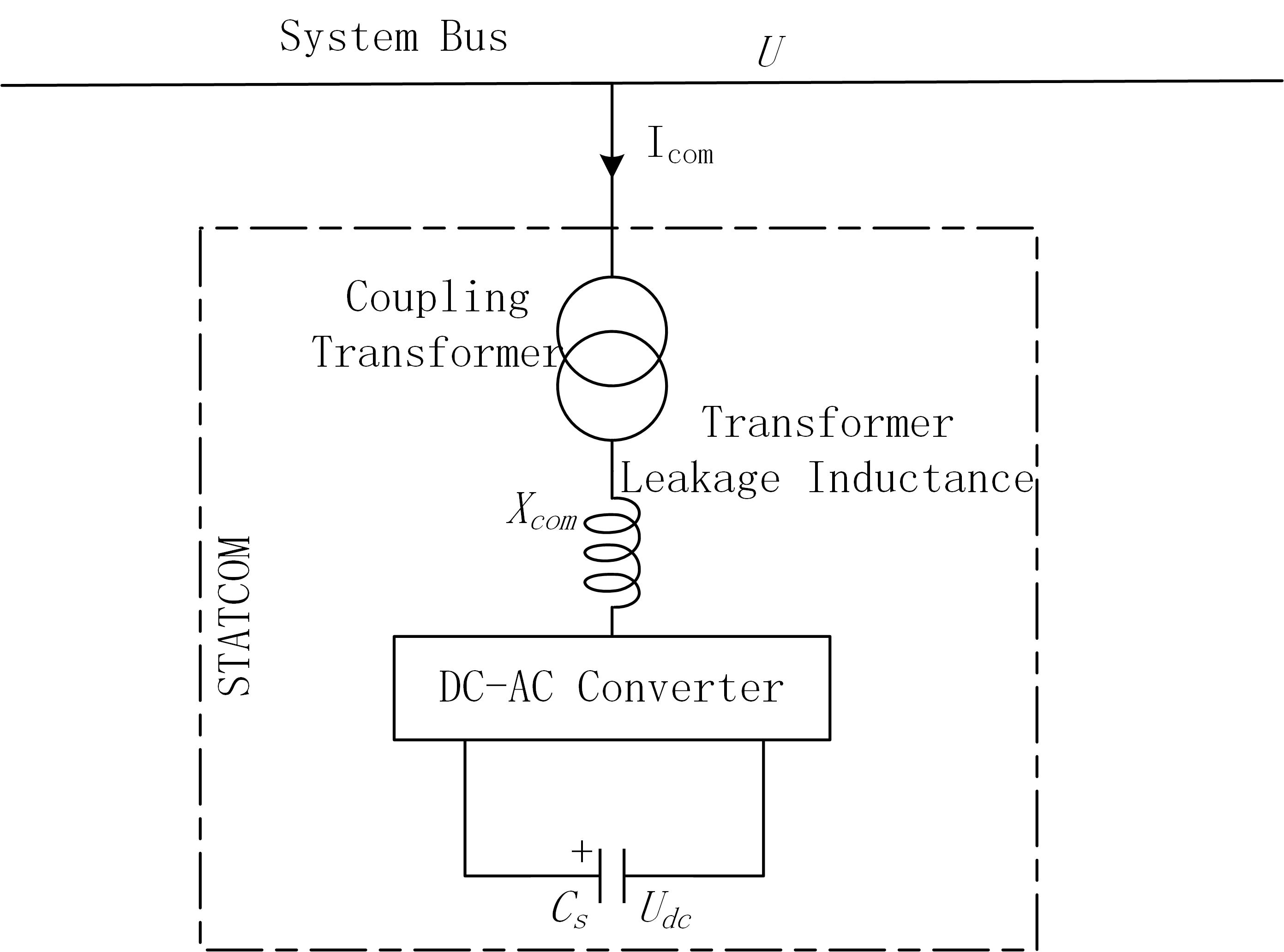
Figure 1. Basic structure of STATCOM. STATCOM: Static synchronous compensator; DC-AC: direct-current to alternating-current.
When the converter output voltage is higher than the PCC voltage under appropriate phase conditions, the STATCOM injects reactive power into the system and supports voltage rise. Conversely, when the converter output voltage is lower, it absorbs reactive power and reduces the bus voltage. Owing to its fast electronic switching and current-limited operation, the STATCOM can provide rapid dynamic voltage regulation, which makes it suitable for auxiliary support during frequency disturbances in islanded microgrids.
In practical implementations, the STATCOM usually adopts a hierarchical control structure. As illustrated in Figure 2, the inner loop performs current control in the dq reference frame to ensure fast response and stable converter operation, while the outer loop regulates voltage or reactive power and can be extended with additional auxiliary control functions. In this paper, this capability is utilized to construct a voltage-load-sensitivity-based auxiliary control strategy for primary frequency regulation. Therefore, the detailed converter switching process is omitted, and the subsequent sections focus on how the proposed open-loop and closed-loop control laws generate the voltage and reactive power commands required for frequency support.
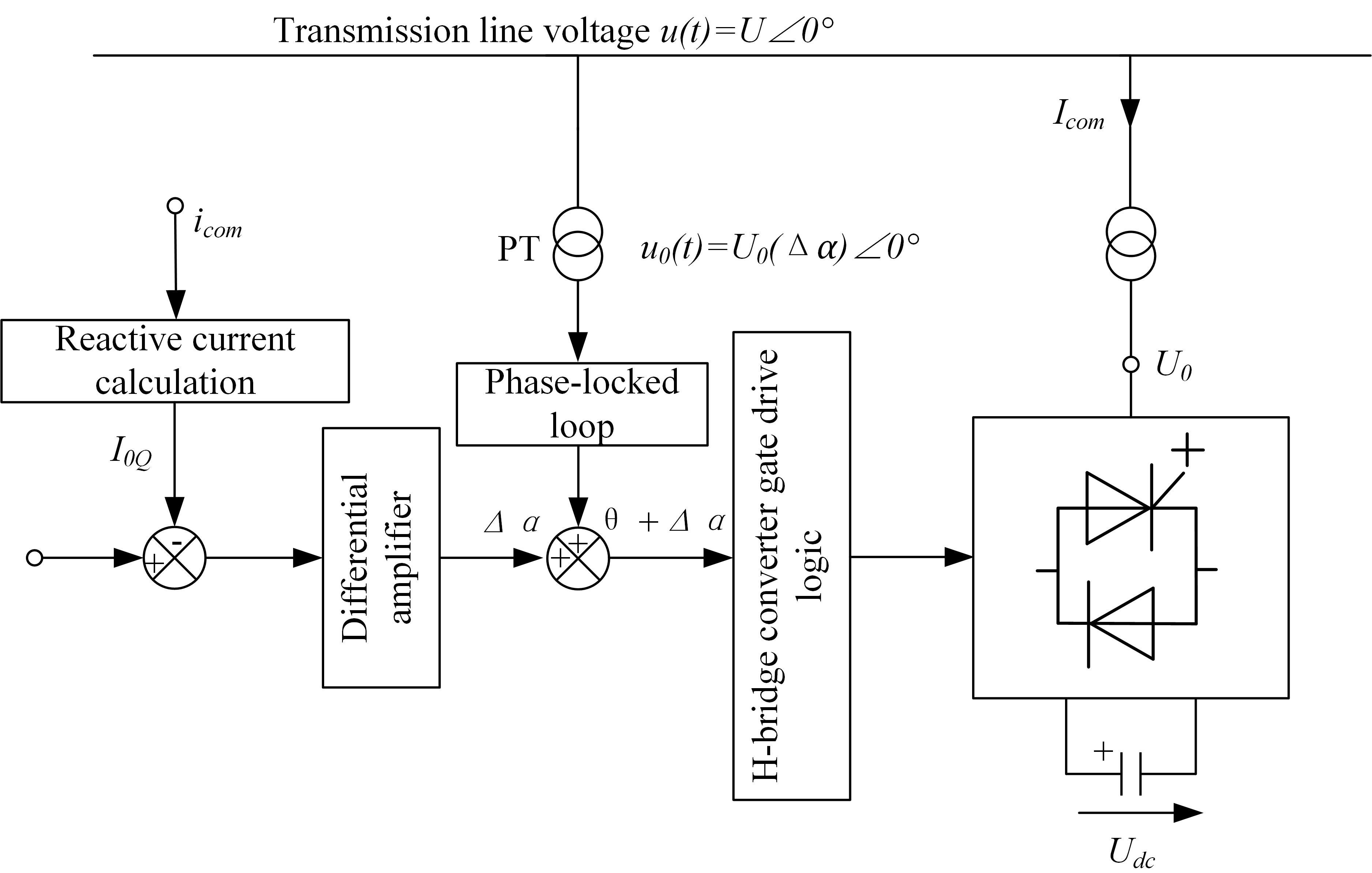
Figure 2. STATCOM control logic diagram. STATCOM: Static synchronous compensator; PT: potential transformer.
3. ESTABLISHMENT OF THE OPEN-LOOP CONTROL MODEL FOR STATCOM-ASSISTED PRIMARY FREQUENCY REGULATION
STATCOM-assisted primary frequency regulation is realized by rapidly reducing the bus voltage during an underfrequency event, thereby decreasing the active power demand of voltage-dependent loads and alleviating the initial power deficit of the microgrid. To improve the clarity of the derivation, the open-loop control model is established in four steps.
A. Voltage-dependent load sensitivity model
The active load is represented by the ZIP load model as follows[20]:
where P0 and V0 denote the rated active load power and nominal bus voltage, respectively, V is the actual operating voltage, kZ, kI and kP are the proportions of constant-impedance, constant-current, and constant-power load components, respectively. By linearizing Equation (1) around the nominal operating point V = V0, the active load voltage sensitivity coefficient can be expressed as:
The expressions for np can be derived in the same manner as that for np, and the corresponding small-signal approximation is:
Similarly, the reactive load variation can be approximated as:
where QL0 is the rated reactive load power, and nq is the reactive power sensitivity coefficient with respect to voltage. Equations (3) and (4) indicate that both active and reactive load powers can be approximately represented by linear voltage sensitivities in the vicinity of the nominal operating point.
B. Target voltage deviation from expected load relief
During an underfrequency event, the proposed open-loop strategy aims to obtain a desired active load reduction ΔPrelief by temporarily lowering the bus voltage. According to Equation (3), the corresponding target voltage deviation can be determined as:
Since the purpose of the proposed control is to reduce the voltage in order to suppress load demand, ΔV* < 0 is imposed during underfrequency operation. The voltage reference is therefore defined as:
Equation (6) shows that the expected active load relief is first converted into an equivalent target voltage reduction, which serves as the direct control objective of the open-loop strategy.
C. Reactive power command required for voltage reduction
To determine the reactive power required from the STATCOM, the external network is represented by a Thevenin equivalent[21].
Under the small-signal approximation, the bus voltage variation can be written as[22]:
When the load-side voltage is intentionally reduced to achieve the desired load relief, the equivalent active power contribution can be approximated as:
Meanwhile, the reactive load also varies with voltage according to Equation (4). Therefore, the STATCOM should provide enough reactive power not only to create the target voltage deviation ΔV*, but also to compensate for the reactive load variation associated with voltage reduction. Combining Equations (4), (8), and (9), the required reactive power command of the STATCOM can be obtained as:
Equation (10) establishes the key link between the desired load relief and the required STATCOM reactive power support. It can be seen that the command depends on the target voltage reduction, the equivalent active power relief, and the voltage sensitivity of the reactive load.
All electrical quantities in Equations (7)-(10), including voltage, active power, reactive power, resistance, and reactance, are expressed in the per-unit system unless otherwise specified.
D. Mapping to STATCOM control variables
After obtaining the reactive power command
where m is the pulse-width modulation (PWM) modulation ratio and k is a fixed proportional coefficient representing the conversion from the DC-side voltage to the AC-side fundamental voltage. The reactive power command is then converted into the q-axis current reference according to:
Accordingly, the open-loop control chain can be summarized as:
This feedforward structure enables the STATCOM to respond rapidly during the early stage of an underfrequency disturbance, thereby reducing bus voltage, suppressing voltage-sensitive load demand, and improving the primary frequency response of the microgrid.
In summary, the STATCOM-assisted primary frequency regulation open-loop control model is shown in Figure 3. Figure 3 represents a feedforward control chain in which the measured frequency dynamics are converted into an expected load-relief signal, then mapped to a target voltage reduction and the corresponding STATCOM reactive power command. The purpose of this structure is to achieve fast equivalent load shedding through temporary voltage depression. In this process, the frequency-related signal reflects the severity of the active power imbalance after the disturbance, and the controller determines the required active load relief according to the voltage sensitivity of the ZIP load model. This expected load-relief signal is then converted into the target voltage deviation and further transformed into the required reactive power command based on the Thevenin-equivalent network relationship. The STATCOM executes this command by adjusting its converter output. Since this structure does not rely on voltage feedback correction, it features a short control path and fast response, which is particularly beneficial before the frequency nadir is formed.
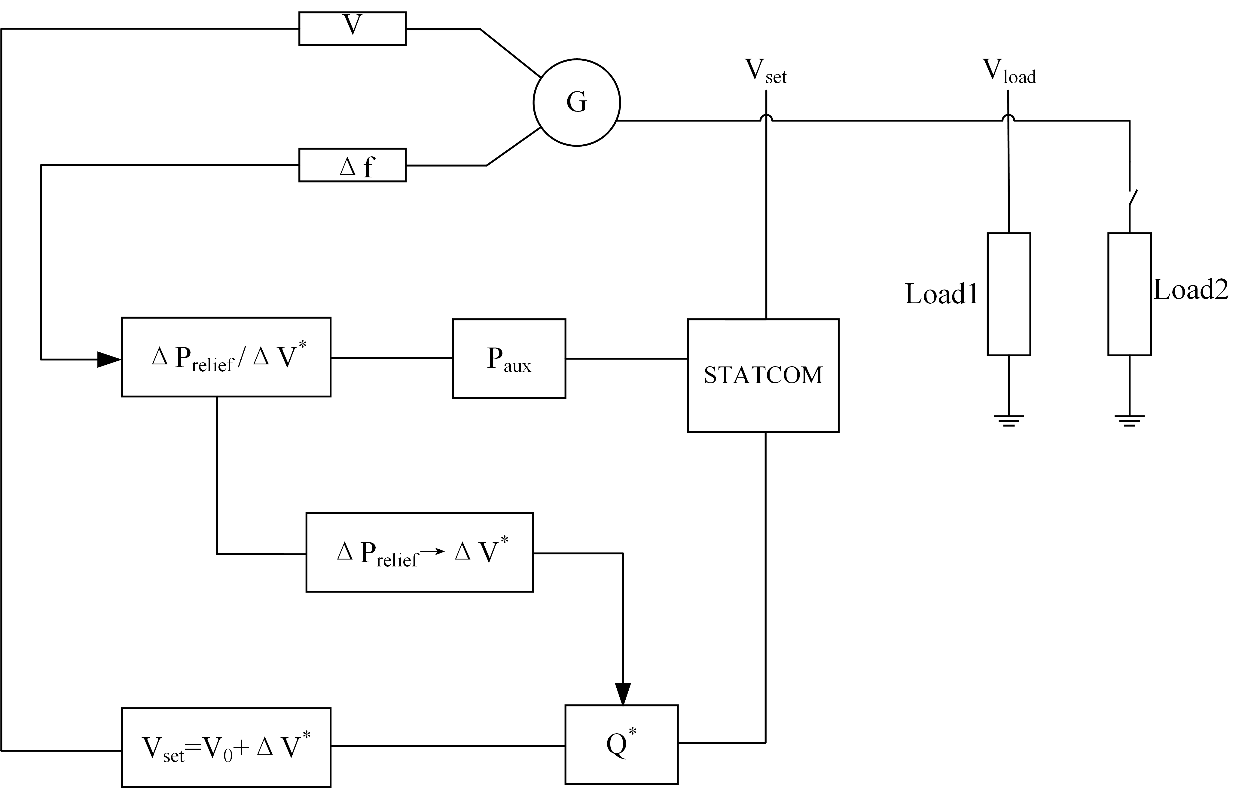
Figure 3. Diagram of STATCOM-assisted primary frequency regulation open-loop control. STATCOM: Static synchronous compensator.
4. ESTABLISHMENT OF THE STATCOM-ASSISTED PRIMARY FREQUENCY REGULATION CLOSED-LOOP CONTROL MODEL
The closed-loop control model is developed as an extension of the open-loop framework described in Section 3. In the open-loop scheme, the voltage reference is directly generated from the expected load relief. In the closed-loop scheme, an additional voltage outer loop is introduced so that the actual bus voltage can track the target voltage deviation more accurately under practical operating conditions.
Figure 4 represents the closed-loop extension of Figure 3, in which the target voltage reduction generated from the frequency signal is further corrected by a voltage outer-loop PI controller. The frequency deviation is first mapped to a target voltage deviation, which is combined with the nominal voltage to form the reference voltage. The actual bus voltage is then compared with this reference, and the resulting voltage error is processed by the PI controller to generate the reactive power command for the STATCOM. In this way, the closed-loop structure maintains the same objective as the open-loop method, namely reducing voltage to suppress the active demand of voltage-sensitive loads, while improving voltage-tracking accuracy under practical operating conditions. However, the additional feedback loop may also introduce dynamic lag and constrain the voltage reduction process. Therefore, in voltage-assisted frequency regulation, the closed-loop scheme may exhibit weaker frequency-support performance than the open-loop control scheme.

Figure 4. Diagram of STATCOM-assisted primary frequency regulation closed-loop control. STATCOM: Static synchronous compensator.
A. Target voltage generation in the closed-loop scheme
To preserve consistency with the open-loop formulation, the frequency deviation is first mapped to a target voltage deviation[23]:
where kf is the frequency-to-voltage mapping coefficient. This coefficient determines the amount of voltage reduction required for a given frequency deviation.
The corresponding voltage reference is defined as:
Thus, the closed-loop strategy retains the same voltage reduction objective as the open-loop strategy, while using feedback to improve the realization of this target.
B. Voltage outer-loop correction
The actual bus voltage V is compared with the reference voltage Vset, and the voltage error is defined as:
A PI controller is then employed in the voltage outer loop to generate the corrected reactive power command:
where Kp and Ki are the proportional and integral gains of the outer-loop controller, respectively.
Equation (17) indicates that the closed-loop controller does not change the control objective itself, but dynamically adjusts the reactive power command according to the voltage tracking error. In this way, the closed-loop scheme can compensate for model mismatch, operating-point changes, and practical actuation constraints.
C. Current reference and PWM implementation
The corrected reactive power command is converted into the q-axis current reference as:
Then, according to the converter voltage relationship:
The PWM modulation ratio m is adjusted to regulate the converter AC-side output voltage and realize the required reactive power response. Therefore, the closed-loop control chain can be summarized as:
Compared with the open-loop strategy, the closed-loop scheme introduces an additional voltage feedback path. This improves voltage tracking capability, but it may also introduce extra dynamic lag and interaction, which helps explain the performance differences observed between the open-loop and closed-loop schemes in the simulation results.
5. SIMULATION ANALYSIS OF STATCOM-ASSISTED OPEN-LOOP FREQUENCY REGULATION CONTROL
All simulations were carried out in MATLAB. The proposed open-loop and closed-loop STATCOM-assisted primary frequency regulation strategies were implemented as control subsystems within the simulation model, including frequency measurement, voltage-reference generation, reactive-power command generation, and STATCOM converter actuation. For the STATCOM-Closed case, the voltage outer-loop PI controller was tuned to make the bus voltage track the target voltage-reduction command without overriding the intended fast voltage depression during the disturbance. The outer-loop gains were selected so that the voltage loop remains slower than the inner reactive-power dynamics, and practical constraints such as deadband, saturation, and rate-limited recovery were included to improve stability and implementation realism. This description has been added to improve the reproducibility of the simulation study. The specific controller parameters are shown in Table 1.
Simulation parameters for STATCOM-assisted open-loop frequency regulation control
| Symbol | Name | Value | Symbol | Name | Value |
| H (s) | Inertia constant | 2.5 | Vs (p.u.) | Thevenin voltage | 1.00 |
| D (p.u./Hz) | Damping coefficient | 2.5 | Rth (Ω) | Equivalent resistance | 0.011 |
| R | Droop coefficient | 0.05 | Xth (Ω) | Equivalent REACTAnce | 0.017 |
| Tg (s) | Governor time constant | 0.35 | ton (s) | Disturbance start time | 1.8 |
| dPstep | Active power disturbance | 2.00 | dQstep | Reactive power disturbance | 2.00 |
| Qmax (kVar) | Maximum reactive power capacity | 4 | tauQ | Response time constant | 0.02 |
| KZ | Constant impedance load factor | 0.60 | KI | Constant current load | 0.40 |
| KP | Constant power load factor | 0.00 |
To compare the impact of different voltage regulation strategies on primary frequency regulation, a unified disturbance scenario and ZIP load model were adopted. A disturbance was introduced at 1.8 s, and three control groups were established: traditional AVR, STATCOM-Open, and AVR+STATCOM-assisted frequency regulation. The simulation parameters are listed in Table 1. The evaluation metrics include the frequency trajectory, the frequency nadir fnadir within the observation window, the max|RoCoF|, the total variation (TV) in the frequency derivative, the minimum voltage Vmin, and the average active load power Pload. Table 2 presents the simulation results for the three cases, and Figure 5 displays the corresponding frequency response curves.
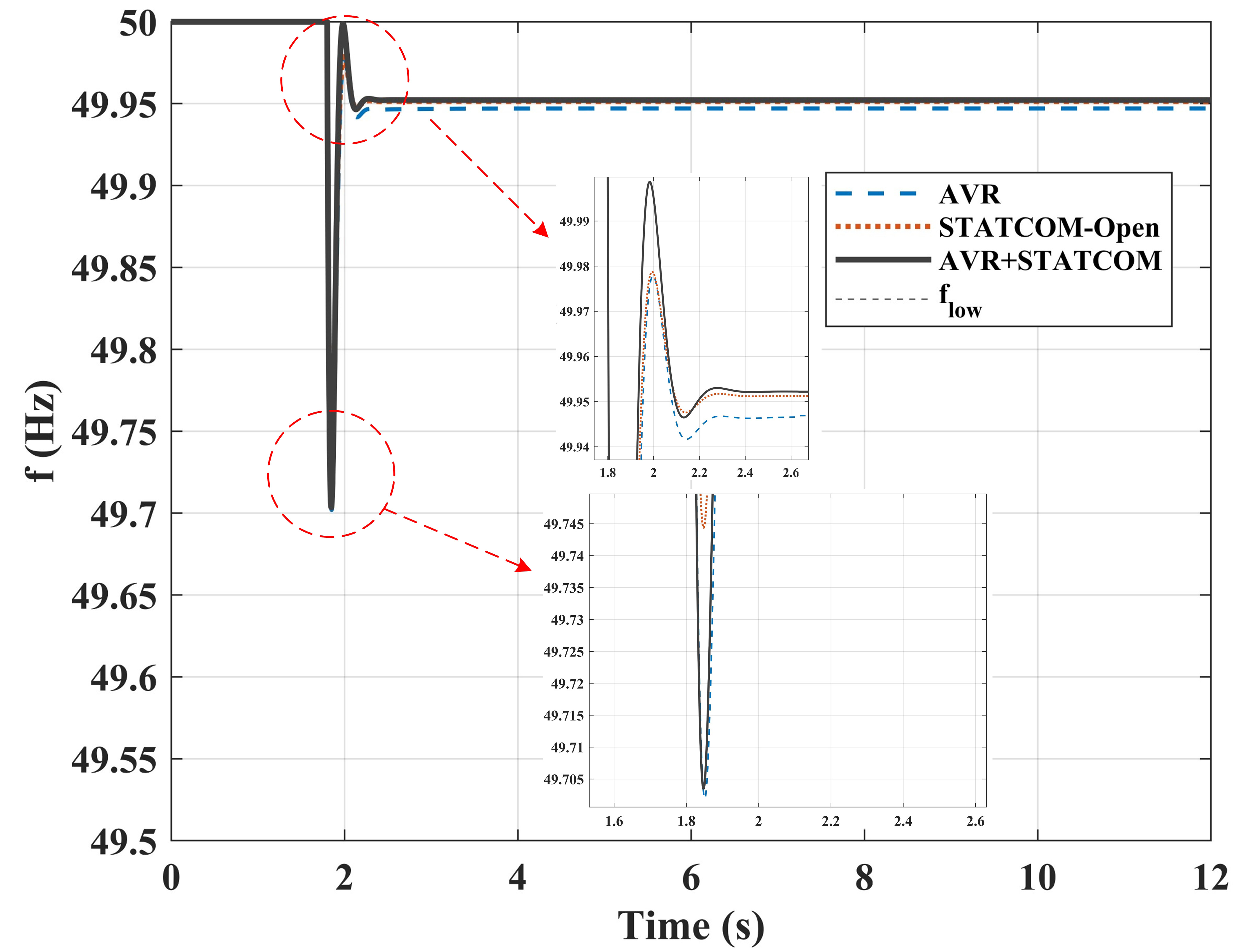
Figure 5. Frequency response of AVR, STATCOM-Open, and AVR+STATCOM. STATCOM: Static synchronous compensator; AVR: automatic voltage regulation.
Simulation results of STATCOM-assisted open-loop frequency regulation control
| Scenario | fnadir (Hz) | max|RoCoF|/(Hz/s) | TV (p.u.) | Vmin (p.u.) | Pload (p.u.) |
| Baseline | 49.701 | 2.678 | 7.6450 | 0.948 | 2.006 |
| AVR | 49.702 | 2.670 | 7.6585 | 0.916 | 1.913 |
| STATCOM-open | 49.746 | 2.293 | 6.5245 | 0.887 | 1.798 |
| AVR+STATCOM | 49.704 | 2.703 | 8.0823 | 0.879 | 1.781 |
Table 2, Figures 5 and 6 demonstrate that, regarding the frequency nadir, the fnadir values for Baseline and AVR are nearly equivalent at 49.701 Hz and 49.702 Hz, respectively. The nadir is significantly elevated to 49.746 Hz by STATCOM-Open, which demonstrates the best performance, while it is increased to 49.704 Hz by AVR+STATCOM, a result similar to that of the traditional AVR. Concerning the RoCoF, the smallest max|RoCoF| value, approximately 2.293 Hz/s, is achieved by STATCOM-Open, whereas the other strategies generally fall within the range of 2.67-2.71 Hz/s. Regarding the smoothness of frequency variations, the smallest TV value, around 6.52, is exhibited by STATCOM-Open, while a slightly higher value of approximately 8.07 is achieved by AVR+STATCOM. This suggests that more flexible adjustment is potentially offered by outer-loop or superimposed control.
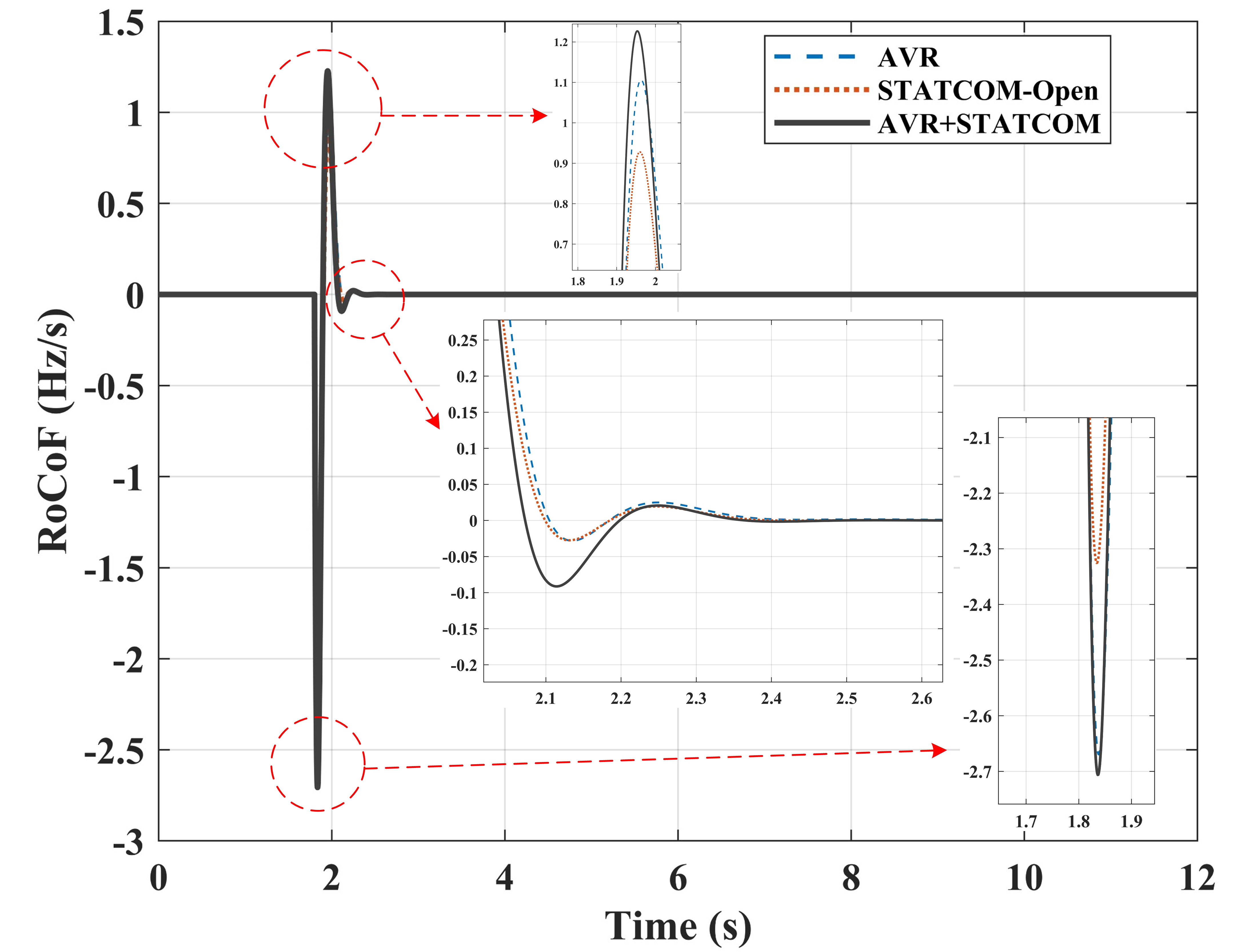
Figure 6. Frequency Rate of Change of AVR, STATCOM-Open, and AVR+STATCOM. STATCOM: Static synchronous compensator; AVR: automatic voltage regulation.
As shown in Figure 7, the lowest bus voltage is obtained under AVR+STATCOM control, with Vmin =
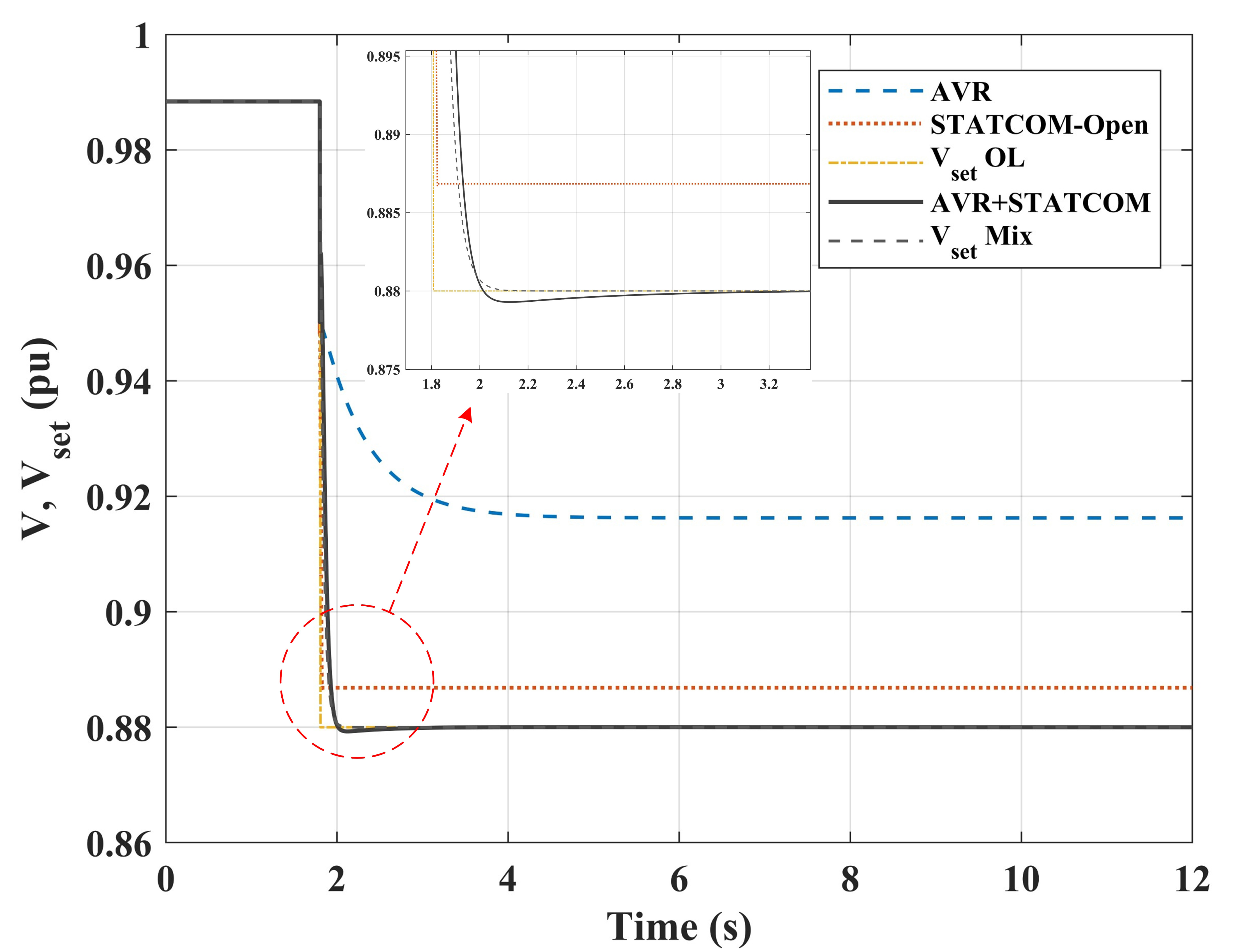
Figure 7. Bus voltage variations in AVR, STATCOM-Open, and AVR+STATCOM. STATCOM: Static synchronous compensator; AVR: automatic voltage regulation.
As presented in Figure 8, the recovery of load active power is divided into three phases. Upon the occurrence of a disturbance, the load step Pload rises sharply, exceeding 2.0 p.u. During the early phase of the disturbance (0-300 ms), Δf is directly mapped to voltage reduction by STATCOM-Open, with a wider slope limit, resulting in the fastest decline in Pload. This explains its superior results for the RoCoF and frequency nadir. Meanwhile, AVR+STATCOM is constrained by the AVR activation timing and slope limits, leading to a slightly slower load reduction in the early stage. As AVR takes effect and some control capability is retained by the STATCOM, a lower voltage is maintained by AVR+STATCOM over a longer duration, causing its recovery phase to be slightly slower than that of STATCOM-Open.
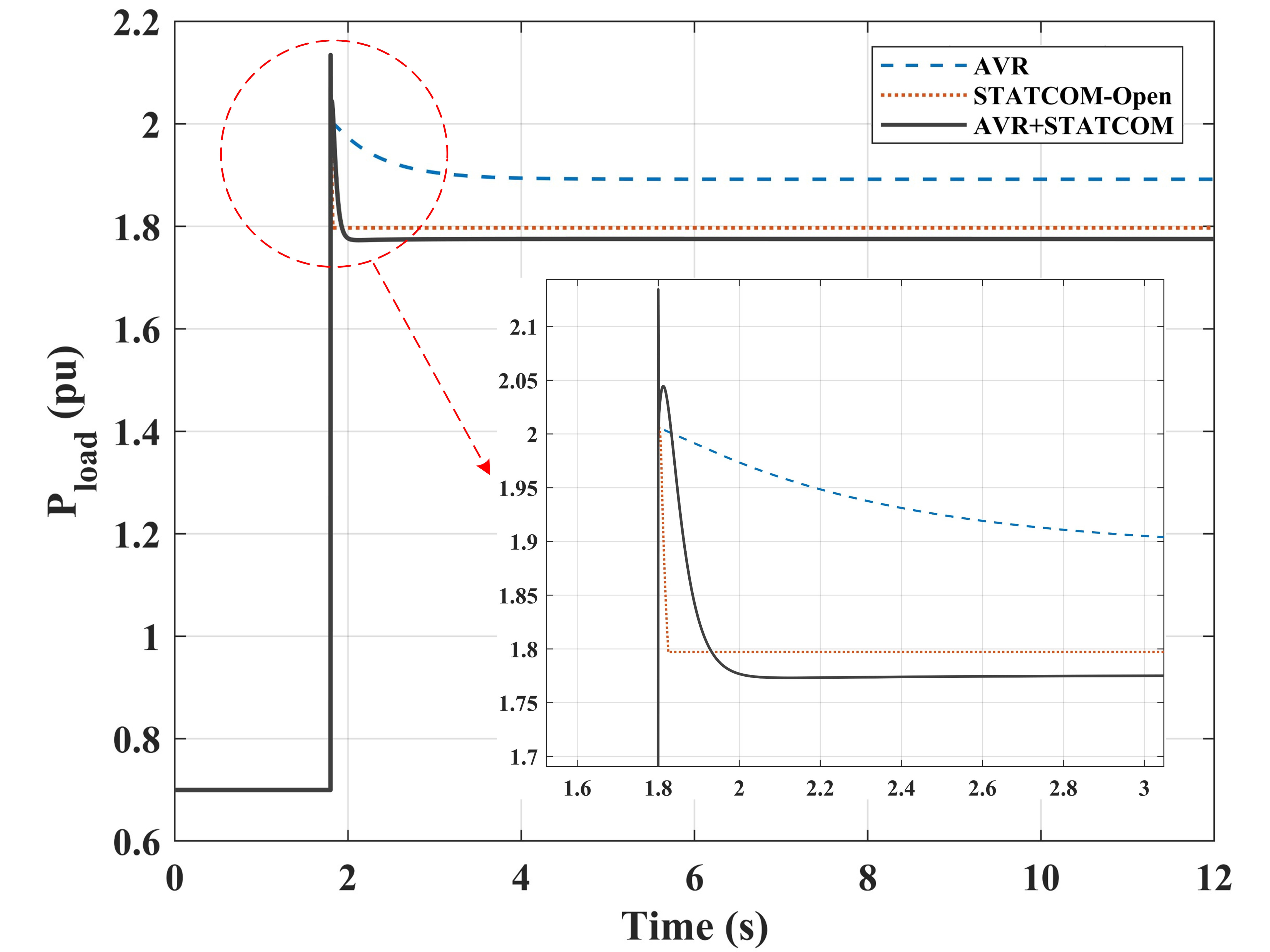
Figure 8. Load active power variations in AVR, STATCOM-Open, and AVR+STATCOM. STATCOM: Static synchronous compensator; AVR: automatic voltage regulation.
These results demonstrate that the static characteristic, in which load shedding is caused by voltage reduction, holds true across all strategies. However, whether voltage reduction translates into a significant improvement in the frequency nadir depends on whether it is accompanied by improved timing and speed before the frequency nadir is formed. Under the current parameters, although a larger voltage drop and a lower average load are achieved by AVR+STATCOM, the primary load reduction is achieved after the frequency nadir, due to the later activation of AVR and the gentler voltage reduction slope. Consequently, a weaker marginal benefit in elevating the nadir is observed, compared to the open-loop approach. In other words, more power is conserved and the total load is reduced to a greater extent by the AVR+STATCOM control scheme, but its main contribution is made after the occurrence of the frequency nadir. In contrast, a more rapid load reduction is achieved by STATCOM-Open, which reduces the power deficit before the nadir is formed.
6. SIMULATION ANALYSIS OF STATCOM-ASSISTED PRIMARY FREQUENCY REGULATION CLOSED-LOOP CONTROL
For further evaluation of the effectiveness of the proposed STATCOM-assisted primary frequency regulation strategy, three control scenarios are compared: traditional AVR (denoted as AVR), STATCOM open-loop control (denoted as STATCOM-Open), and STATCOM closed-loop control (denoted as STATCOM-Closed). A unified event and model are adopted for the evaluation, with a focus on four aspects: frequency response, RoCoF, bus voltage, and load active power. The frequency response curves for Baseline, AVR, STATCOM-Open, and STATCOM-Closed are illustrated in Figure 9, and the corresponding simulation results are summarized in Table 3.
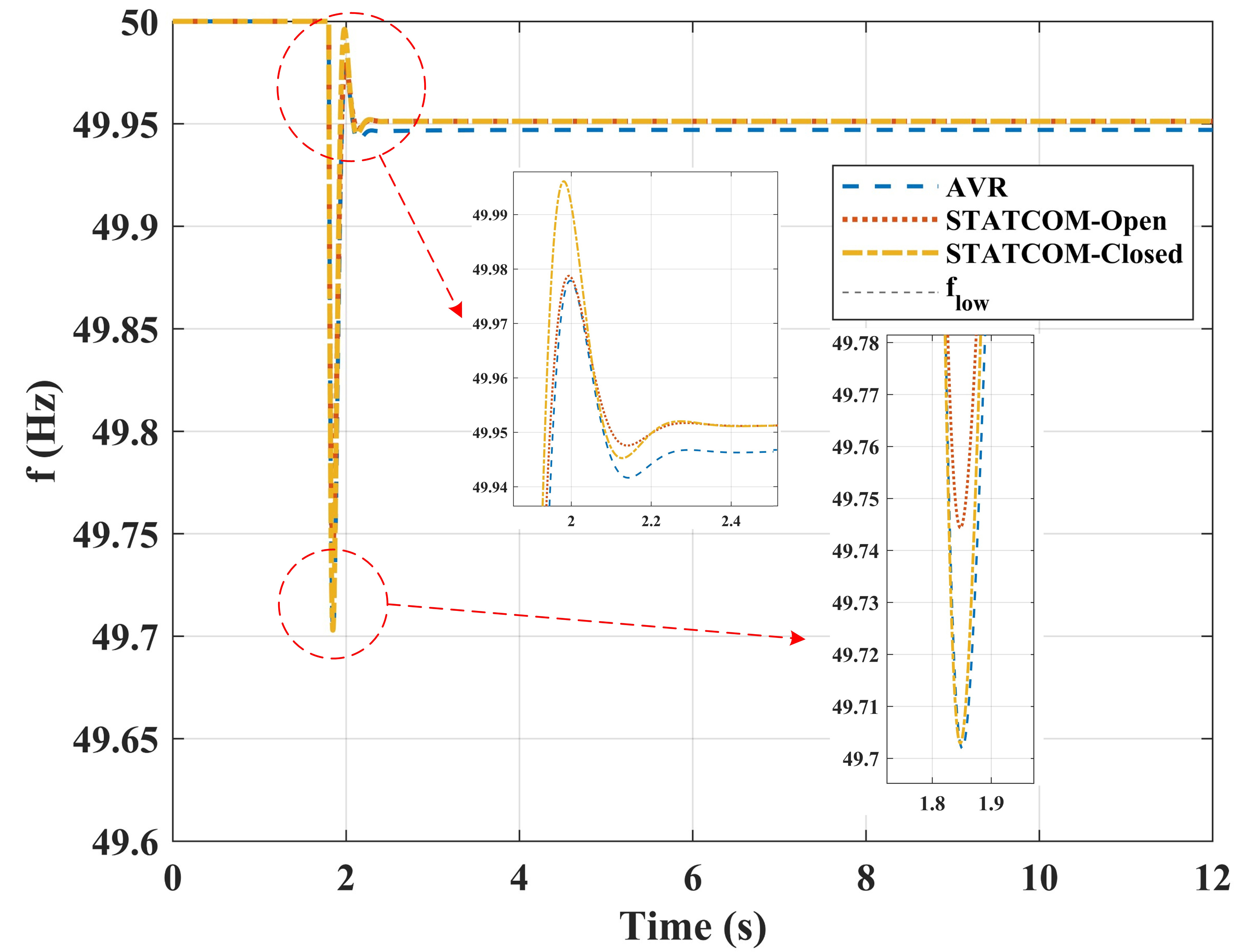
Figure 9. Frequency response of AVR, STATCOM-Open, and STATCOM-Closed. STATCOM: Static synchronous compensator; AVR: automatic voltage regulation.
Simulation results of STATCOM-assisted closed-loop frequency regulation control
| Scenario | fnadir (Hz) | max|RoCoF|/(Hz/s) | TV (Hz/s) | Vmin (p.u.) | Pload (p.u.) |
| Baseline | 49.701 | 2.678 | 7.6450 | 0.948 | 2.006 |
| STATCOM-open | 49.746 | 2.293 | 6.5245 | 0.887 | 1.798 |
| STATCOM-closed | 49.703 | 2.707 | 8.0691 | 0.887 | 1.802 |
As shown in Figure 9, after the occurrence of a disturbance, the highest frequency nadir is achieved under STATCOM-Open control, reaching 49.746 Hz, which is approximately 0.044 Hz higher than the value of 49.702 Hz achieved under AVR control. A frequency nadir of 49.703 Hz is achieved by the STATCOM-Closed control method, a value close to that achieved by the AVR control method. In all three cases, the frequency then converges rapidly to around 49.95 Hz after 2 s. These results indicate that a stronger voltage drop is indirectly associated with a smaller frequency decline. Furthermore, due to its larger target voltage reduction magnitude and rapid execution, the most significant improvement in the frequency nadir during the primary event is achieved by the open-loop strategy. Under the current parameters, a limited impact on the frequency nadir is observed for the closed-loop strategy.
As shown in Figure 10, the maximum RoCoF under STATCOM-Open control is measured as 2.293 Hz/s, which is significantly lower than the value of 2.670 Hz/s obtained with AVR control. This result indicates that the initial decline in dynamic frequency is suppressed by the open-loop voltage reduction. The maximum RoCoF under STATCOM-Closed reaches 2.707 Hz/s, a value slightly higher than that of the AVR case. When combined with the frequency response curve in Figure 9, it is observed that the feedback, hold, release, and slope settings of the closed-loop outer control introduce slight additional dynamics under the present tuning, which prevents further reduction of the RoCoF peak. It is therefore suggested that, for the closed-loop strategy to achieve a superior RoCoF, better coordination among the outer-loop gain, hold time, and recovery slope is required.
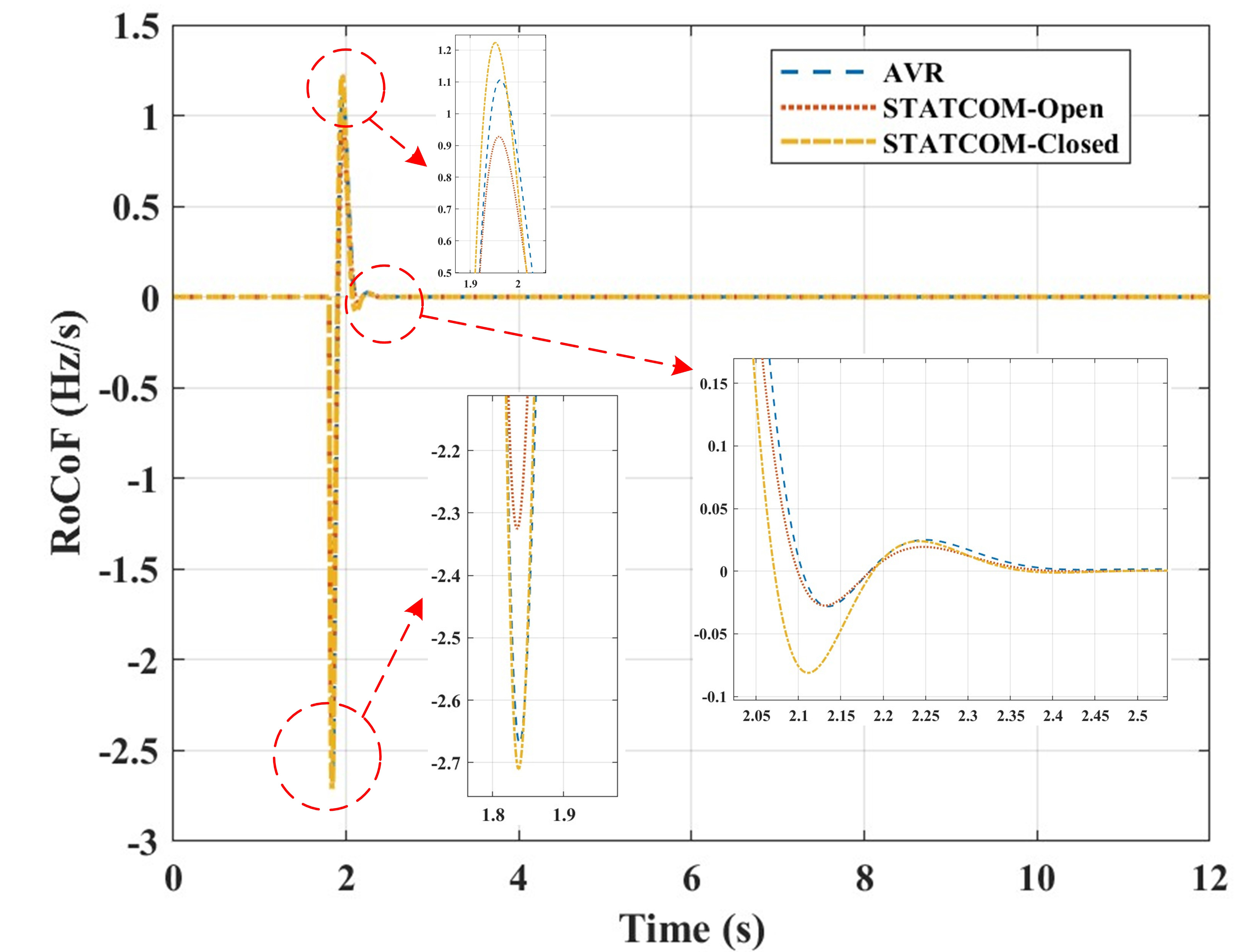
Figure 10. Frequency Rate of Change of AVR, STATCOM-Open, and STATCOM-Closed. STATCOM: Static synchronous compensator; AVR: automatic voltage regulation.
As shown in Figure 11, the minimum voltage Vmin under AVR control is 0.916 p.u., whereas both STATCOM strategies maintain voltages around 0.887 p.u. After the disturbance, the voltage is quickly stabilized between 0.885 p.u. and 0.887 p.u. The voltage curves demonstrate that the voltage is actively reduced by the STATCOM through regulation, thereby lowering the load’s active power demand following the voltage reduction. Both STATCOM schemes produce a deeper and more sustained voltage sag, which reduces the load power demand during primary frequency regulation. In contrast, the voltage reduction achieved by the AVR is much smaller.
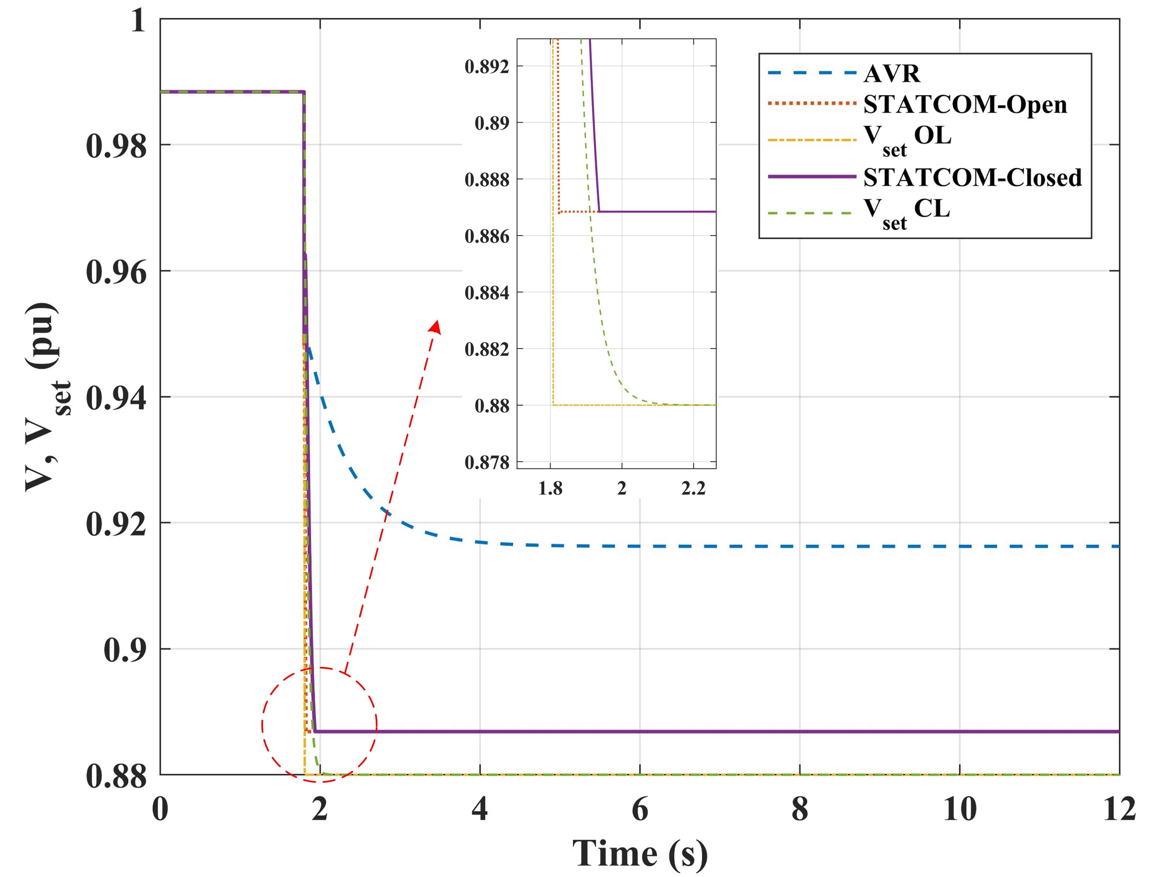
Figure 11. Bus voltage variations in AVR, STATCOM-Open, and STATCOM-Closed. STATCOM: Static synchronous compensator; AVR: automatic voltage regulation.
As shown in Figure 12, the average active load power Pload is 1.913 p.u. for the AVR case, and 1.798 p.u. for both STATCOM-Open and STATCOM-Closed. This corresponds directly with the voltage trajectories: a lower and more stable voltage results in reduced active load demand, which in turn leads to a higher frequency nadir. Owing to its larger voltage-reduction setting, the most significant active load reduction is achieved by the open-loop strategy, thereby explaining its highest frequency nadir and minimum RoCoF. Although the closed-loop strategy also reduces the voltage to 0.887 p.u., its closed-loop adjustments - involving feedback, limiting, and hold coordination - slightly increase the TV and diminish the improvements in frequency nadir and RoCoF.
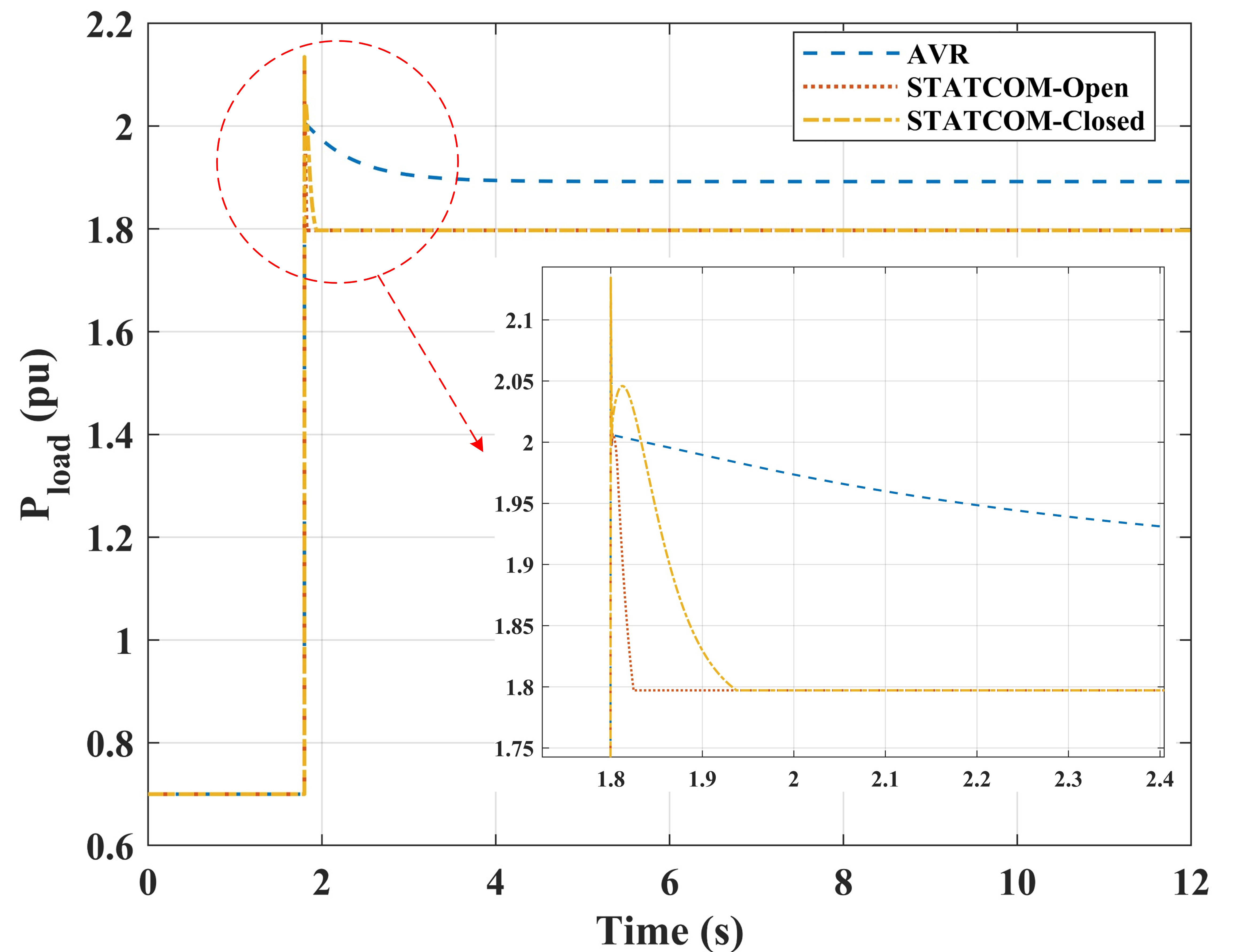
Figure 12. Load active power variations in AVR, STATCOM-Open, and STATCOM-Closed. STATCOM: Static synchronous compensator; AVR: automatic voltage regulation.
The proposed STATCOM-assisted open-loop primary frequency regulation control method is able to most rapidly generate a deterministic voltage reduction during the initial stage of a disturbance. Consequently, the early load demand is effectively reduced and the initial power deficit is mitigated, which is directly reflected in a smaller RoCoF and a higher frequency nadir fnadir. In contrast, the closed-loop outer control and the AVR+STATCOM hybrid scheme are constrained by activation timing, slope limits, and PI dynamics. As a result, the available voltage reduction and load shedding in the early stage are not fully utilized, leading to a lower level of improvement compared with the open-loop control.
7. CONCLUSION
A supplementary control strategy, namely, CVR, is proposed. This strategy is centered on voltage-sensitive loads and enables a rapid local reduction in the controlled node voltage during underfrequency events through a feedforward mapping from Δf to ΔPrelief to ΔV*. Equivalent load shedding is thereby achieved with minimal energy cost, and the primary frequency response of microgrids is improved. To validate the practicality of the proposed strategy, a unified operating condition model is developed and calibrated, with comparative simulations designed for three scenarios: AVR, STATCOM-Open, and AVR+STATCOM. The simulation results demonstrate that the open-loop scheme significantly elevates the frequency nadir from approximately 49.701 Hz to 49.746 Hz, reduces the maximum RoCoF from about 2.67-2.71 Hz/s to 2.293 Hz/s, and yields the smallest total variation in the frequency derivative. Under the current settings, the improvements in the frequency nadir and RoCoF provided by the closed-loop outer control are weaker than those provided by the open-loop approach. This occurs because the change of reactive power is restricted by the closed-loop control strategy, thereby limiting the amplitude of voltage change. As a result, the frequency regulation effect is also limited. The simulation analysis indicates that the key to converting the coupling benefits of voltage and frequency into improved frequency metrics lies in rapidly reducing the voltage before the nadir forms and maintaining a slow voltage recovery. In terms of engineering applications, this supplementary control extends the functionality of STATCOMs from power-quality and voltage regulation to rapid primary frequency support, making it suitable for islanded or campus-type microgrids with a high proportion of voltage-dependent loads and permissible voltage reduction ranges. Combined with multi-scenario deployment and parameter zoning, this strategy shows potential for further enhancing overall frequency stability. Future work will focus on adaptive parameter tuning for different topologies and operating states, as well as the investigation of coordinated control strategies with grid-forming inverters.
DECLARATIONS
Authors’ contributions
Writing - review & editing, writing - original draft, methodology: Li, C.; Zhou, B.
Writing - review & Editing, Supervision, Methodology, Funding Acquisition: Wang, H.; Li, Z.
Investigation, data curation: Yao, Z.; Liu, Z.
Investigation: Wu, Z.
Availability of data and materials
The raw data supporting the conclusions of this article will be made available by the authors upon request.
AI and AI-assisted tools statement
Not applicable.
Financial support and sponsorship
This work was supported by the National Natural Science Foundation of China (U22B20115).
Conflicts of interest
Yao, Z. is affiliated with the State Grid Dandong Electric Power Supply Company, while the other authors have declared that they have no conflicts of interest.
Ethical approval and consent to participate
Not applicable.
Consent for publication
Not applicable.
Copyright
© The Author(s) 2026.
REFERENCES
1. Li, Y.; Yu, C.; Shahidehpour, M.; Yang, T.; Zeng, Z.; Chai, T. Deep reinforcement learning for smart grid operations: algorithms, applications, and prospects. Proc. IEEE. 2023, 111, 1055-96.
2. Hatziargyriou, N.; Milanovic, J.; Rahmann, C.; et al. Definition and classification of power system stability – revisited & extended. IEEE. Trans. Power. Syst. 2021, 36, 3271-81.
3. Hong, F.; Pang, Y.; Ji, W.; et al. Assessment and enhancement of FRC of power systems considering thermal power dynamic conditions. CSEE. J. Power. Energy. Syst. 2024,. 10, 1371-83. .
4. Arrano-vargas, F.; Konstantinou, G. Modular design and real-time simulators toward power system digital twins implementation. IEEE. Trans. Ind. Inf. 2023, 19, 52-61.
5. Li, H.; Ren, Z.; Trivedi, A.; Verma, P. P.; Srinivasan, D.; Li, W. A noncooperative game-based approach for microgrid planning considering existing interconnected and clustered microgrids on an island. IEEE. Trans. Sustain. Energy. 2022, 13, 2064-78.
6. Zia, M. F.; Benbouzid, M.; Elbouchikhi, E.; Muyeen, S. M.; Techato, K.; Guerrero, J. M. Microgrid transactive energy: review, architectures, distributed ledger technologies, and market analysis. IEEE. Access. 2020, 8, 19410-32.
7. Bidram, A.; Poudel, B.; Damodaran, L.; Fierro, R.; Guerrero, J. M. Resilient and cybersecure distributed control of inverter-based islanded microgrids. IEEE. Trans. Ind. Inf. 2020, 16, 3881-94.
8. Hussain, A.; Hasan, S.; Patil, S.; Shireen, W. Fast frequency regulation in islanded microgrid using model-based load estimation. IEEE. Trans. Energy. Convers. 2021, 36, 3188-98.
9. Khayat, Y.; Shafiee, Q.; Heydari, R.; et al. On the secondary control architectures of AC microgrids: an overview. IEEE. Trans. Power. Electron. 2020, 35, 6482-500.
10. Parvizimosaed, M.; Zhuang, W. Enhanced active and reactive power sharing in islanded microgrids. IEEE. Syst. J. 2020, 14, 5037-48.
11. Liu, R.; Lin, Z.; Zhang, H.; Li, Y. Analysis and mitigation of inner voltage control’s negative damping effect on active power oscillations in multi-VSG systems. IEEE. Trans. Power. Electron. 2026, 41, 3924-39.
12. Cheema, K. M. A comprehensive review of virtual synchronous generator. Int. J. Electr. Power. Energy. Syst. 2020, 120, 106006.
13. Zhang, Q.; Li, G. Experimental study on a semi-active battery-supercapacitor hybrid energy storage system for electric vehicle application. IEEE. Trans. Power. Electron. 2020, 35, 1014-21.
14. Gutierrez-lagos, L.; Ochoa, L. F. OPF-based CVR operation in PV-Rich MV-LV distribution networks. IEEE. Trans. Power. Syst. 2019, 34, 2778-89.
15. Varma, R. K.; Mohan, S. Mitigation of fault induced delayed voltage recovery (FIDVR) by PV-STATCOM. IEEE. Trans. Power. Syst. 2020, 35, 4251-62.
16. Mohanty, S.; Das, A.; Singh, B. Improved synthetic inertia support by a hybrid CHB-STATCOM for dynamic frequency control in a high inverter-based-resources network. IEEE. Trans. Ind. Appl. 2024, 60, 7240-9.
17. Guo, J.; Li, W.; Pan, X.; et al. Frequency response model for power systems including HVDC-connected offshore wind power with communication-free frequency control. IEEE. Trans. Circuits. Syst. I. 2026, 73, 2195-205.
18. Munkhchuluun, E.; Gunaruwan Meegahapola, L.; Vahidnia, A. Reactive power assisted frequency regulation scheme for large-scale solar-PV plants. Int. J. Electr. Power. Energy. Syst. 2023, 146, 108776.
19. Khalid, M.; Khan, K. A. Discussion on “mitigation of fault induced delayed voltage recovery (FIDVR) by PV-STATCOM”. IEEE. Trans. Power. Syst. 2022, 37, 1665.
20. Pinto, J. H. D. G.; Amorim, W. C. S.; Cupertino, A. F.; Pereira, H. A.; Junior, S. I. S.; Teodorescu, R. Optimum design of MMC-based ES-STATCOM systems: the role of the submodule reference voltage. IEEE. Trans. Ind. Appl. 2021, 57, 3064-76.
21. Ranjbar, S. STATCOM-based intelligent wide-area controller for damping interarea oscillation. IEEE. Syst. J. 2023, 17, 4062-9.
22. Kaymanesh, A.; Chandra, A.; Al-haddad, K. Model predictive control of MPUC7-based STATCOM using autotuned weighting factors. IEEE. Trans. Ind. Electron. 2022, 69, 2447-58.
Cite This Article
How to Cite
Download Citation
Export Citation File:
Type of Import
Tips on Downloading Citation
Citation Manager File Format
Type of Import
Direct Import: When the Direct Import option is selected (the default state), a dialogue box will give you the option to Save or Open the downloaded citation data. Choosing Open will either launch your citation manager or give you a choice of applications with which to use the metadata. The Save option saves the file locally for later use.
Indirect Import: When the Indirect Import option is selected, the metadata is displayed and may be copied and pasted as needed.
About This Article
Copyright

Data & Comments
Data
0


Comments
Comments must be written in English. Spam, offensive content, impersonation, and private information will not be permitted. If any comment is reported and identified as inappropriate content by OAE staff, the comment will be removed without notice. If you have any queries or need any help, please contact us at support@oaepublish.com.