

Amine-mediated, oxygen-tolerant concerted capture and electrochemical conversion of CO2 from flue gas
 0
0 Abstract
Integrated capture and electrochemical conversion of CO2 from flue gas can mitigate the energy penalties of conventional decoupled processes, offering a promising pathway to reduce CO2 emissions and valorize carbon resources. However, this strategy has not yet been fully realized because of the mismatch between the rates of CO2 capture and electrolysis. Herein, we report a concerted system integrating CO2 capture and electrochemical conversion from flue gas using monoethanolamine (MEA) as the mediator. MEA captures CO2 from flue gas and delivers it in liquid form to an electrolyzer, where the captured CO2 is electrochemically converted into CO with concurrent MEA regeneration. The regenerated MEA is recycled to the absorber for another round of CO2 capture, establishing a sustainable closed loop for simultaneous CO2 capture and electrolysis. Owing to the low solubility of O2 in the MEA solution, the system exhibits strong oxygen tolerance, avoiding efficiency loss caused by the competing oxygen reduction reaction. By examining key parameters such as current density, electrode hydrophobicity, and CO2 concentration, the concerted system achieves a high CO2 capture efficiency of 63% for flue gas containing 15% CO2 and produces a syngas with an H2/CO = 3.2 over 24 h of operation. This work demonstrates the first MEA-based system for concerted capture and conversion of CO2 from flue gas, offering an effective strategy for sustainable carbon recycling and syngas production.
Keywords
INTRODUCTION
The continuous rise in atmospheric CO2 concentrations has led to severe environmental issues, including global warming, ocean acidification, and biodiversity loss[1,2]. Carbon capture and utilization (CCU) technologies have garnered increasing attention due to their capability of reducing CO2 emissions while simultaneously producing value-added chemicals and fuels[3-5]. For example, porous materials have been widely studied for CO2 capture and catalytic conversion, due to their high surface area and tunable structures[6-8]. Among CCU technologies, electrochemical CO2 reduction reaction (CO2RR) is particularly promising, because it can use renewable electricity (e.g., wind and solar power) to convert CO2 under mild conditions into a variety of valuable products such as CO and formic acid[9,10]. Currently, most studies on CO2RR are performed using high-purity CO2 gas in lab-scale electrolyzers. In practice, industrial flue gas, the main point source of anthropogenic CO2 emissions, contains 5%-15% CO2 mixed with N2, O2, and other gas impurities. Direct electrolysis of flue gas in gas-fed electrolyzers is challenging because the presence of O2 severely hinders CO2RR by triggering the thermodynamically more favorable oxygen reduction reaction (ORR), resulting in reduced selectivity and increased energy loss [Figure 1, Path I][11,12]. Moreover, the low CO2 concentration in the flue gas leads to low reaction efficiency[13,14].
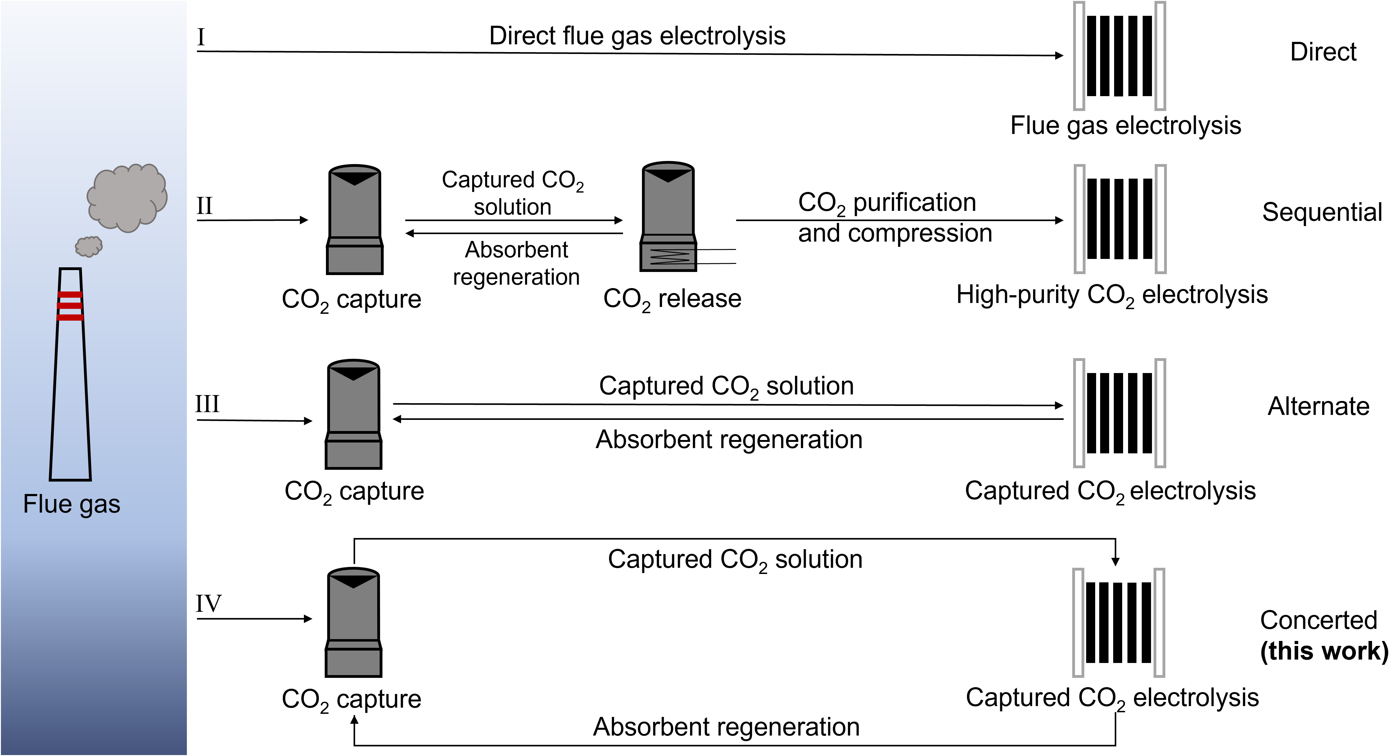
Figure 1. Schematic illustration of various pathways for CO2 valorization from industrial flue gas. Path I represents the direct flue-gas electrolysis in gas-fed electrolyzers without capture steps. Path II illustrates a sequential route for CO2 capture and electrolysis, with electrolysis also carried out in a gas-fed electrolyzer. Path III depicts the alternate route in which captured CO2 is directly converted via electrolysis of the captured CO2 solution, while the regenerated absorbent is reused for subsequent CO2 capture. Path IV shows the concerted route for simultaneous CO2 capture and electrolysis reported in this work.
To overcome these issues, a sequential approach for CO2 capture and conversion from flue gas has been widely adopted [Figure 1, Path II][15-17]. In this process, CO2 is first absorbed from flue gas using alkaline absorbents such as KOH or amine solutions, forming captured CO2 solutions enriched with (bi)carbonates or carbamates. This is usually followed by thermal treatment to release CO2 while simultaneously regenerating the absorbent. The purified CO2 is compressed and transported for subsequent conversion in a gas-fed electrolyzer[18]. Although effective at separating CO2 from flue gas and converting it, this approach involves high energy consumption and capital investment, limiting its economic viability[19,20]. For instance, capturing CO2 using a commercial absorbent such as monoethanolamine (MEA) requires up to
Electrochemical conversion of captured CO2 solution has recently emerged as a promising alternative to the conventional sequential CO2 capture and conversion approach, offering the potential to simplify the overall process and reduce energy consumption [Figure 1, Path III][24]. In this strategy, CO2 capture and conversion occur alternately: CO2 is captured by alkaline absorbents such as carbonates or MEA to form a captured CO2 solution, which is then fed into an electrolyzer where CO or other products are electrochemically produced. After the reaction, the regenerated alkaline absorbent can be reused for another round of CO2 capture and conversion. For instance, Zhang et al. reported the direct electrolysis of captured CO2 solution (i.e., bicarbonate, obtained by capturing CO2 in a carbonate solution) in a membrane electrode assembly with a silver foam cathode, achieving a Faraday efficiency for CO (FECO) of 60%[25]. Later, Song et al. developed a Ni-based single-atom catalyst (Ni-SAC) for electrolysis of KHCO3 solution, achieving a much higher FECO exceeding 90%[26]. In comparison, Leverick et al. attained a relatively low FECO of ~19% when employing a simple Ag foil electrode to electrolyze a CO2-capturing MEA solution[27].
While path III effectively integrates CO2 capture and conversion, it relies on pre-captured CO2. During extended electrolysis, the consumption of captured CO2 without replenishment decreases its concentration, leading to a drop in product selectivity[28]. This limitation highlights the need for a concerted CO2 capture and conversion system operating simultaneously. However, such a strategy has not yet been realized due to the inherent mismatch between the rates of CO2 capture and electrolysis. This raises a critical question: can the electrolytically regenerated absorbent maintain adequate alkalinity to capture CO2 effectively and sustain the supply of captured CO2 species for subsequent conversion cycles at comparable rates[29,30]? Recent work has demonstrated a coupled system comprising a K2CO3 absorption column and an electrolyzer, which achieved a CO2 capture efficiency of 30% and an FECO of 35%, validating the feasibility of such a concerted approach[31]. Nonetheless, carbonate-based absorbent solutions suffer from slow CO2 absorption kinetics, hindering their practical applications[32]. In comparison, MEA exhibits faster reaction kinetics and higher industrial maturity for CO2 capture, making it a more promising candidate for practical deployment[33,34].
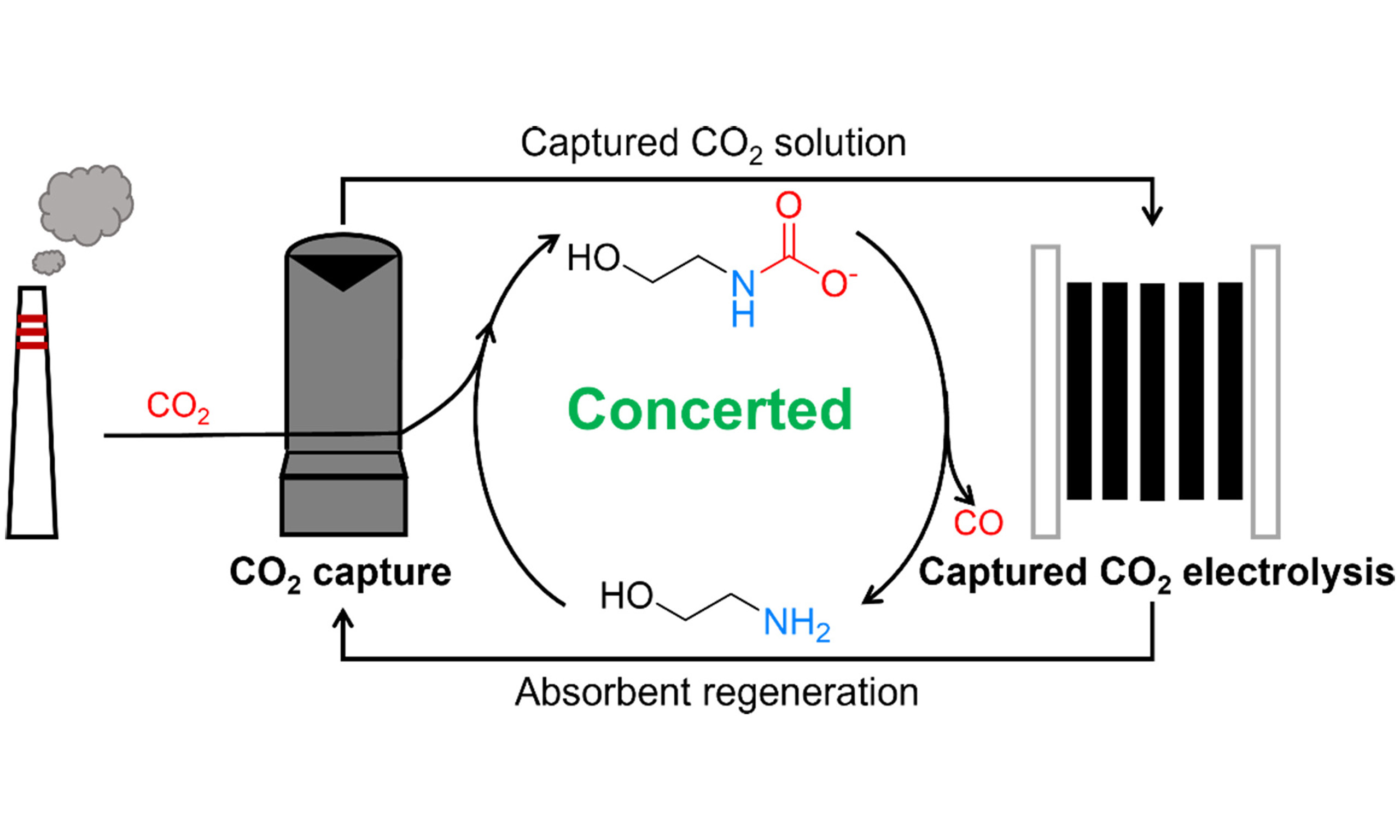
Herein, we report an MEA-based concerted CO2 capture-conversion system by coupling a CO2 absorber with a liquid-fed electrolyzer for continuous syngas production from simulated flue gas (containing 15% CO2, 5% O2, and 80% N2) [Figure 1, Path IV]. A bipolar membrane (BPM) is utilized to generate protons, which react with the carbamate/bicarbonate species formed during CO2 capture in MEA, enabling in situ CO2 liberation for subsequent electrochemical reduction to CO. Meanwhile, MEA is regenerated and recycled back to capture additional CO2, forming a concerted system for simultaneous CO2 capture and electrochemical conversion. During electrolysis, H2 is also produced from the reduction of protonated MEA generated during CO2 capture, forming a syngas with H2/CO = 3.2. In situ electrochemical spectroscopy is performed to elucidate the reaction processes occurring at the electrode surface.
EXPERIMENTAL
Chemicals and materials
Chemicals
Nickel chloride hexahydrate (NiCl2∙6H2O), melamine (C3H6N6), potassium hydroxide (KOH), polytetrafluoroethylene suspension (PTFE, 60 wt%), and MEA were purchased from Shanghai Aladdin Bio-Chem Technology Co., Ltd. Lithium chloride (LiCl) and potassium chloride (KCl) were obtained from Shanghai Maclin Biochemical Technology Co., Ltd. Nafion solution (5 wt%) was purchased from Sigma-Aldrich Chemical Reagent Co., Ltd. Methanol, ethanol, and isopropanol were acquired from Sinopharm Chemical Reagent Co., Ltd. Polyethylene terephthalate (PET) plastic waste was acquired from used Nongfu Spring mineral water bottles. All reagents used in this work were obtained from commercial suppliers and used without further purification.
Catalyst synthesis
The catalyst was synthesized according to a reported procedure[35]. A homogeneous mixture was prepared by grinding 1.0 g of NiCl2·6H2O, 2.0 g of melamine, 5.5 g of KCl, and 4.5 g of LiCl in a mortar. Next,
Electrochemical measurements
Electrolysis of simulated flue gas
The working electrode was prepared as follows:
Electrolysis of the CO2-capturing MEA solution
The working electrodes were prepared as follows: a mixture of 16 mg of the catalyst, 16 μL of Nafion solution (5 wt%), and 3.6 mL of isopropanol was sonicated for 30 min. The resulting suspension was drop-cast onto a hydrophilic carbon paper (TGP-H-060) with an effective area of 1 cm2, achieving a catalyst loading of
Concerted CO2 capture and electrolysis
Before initiating the concerted capture and electrolysis process, simulated flue gas (15% CO2/5% O2/80% N2 or 5% CO2/5% O2/90% N2) was introduced at a flow rate of 50 sccm into an MEA solution for CO2 capture. The pH of the solution was monitored using a pH meter (Hangzhou Meiyi, SUP-PH6.5- 5022-YK-IFS15, China). When the CO2 capture was completed, electrolysis was initiated, and CO2 capture and electrolysis were carried out simultaneously under continuous flue gas feeding at a flow rate of 5 sccm. The CO2-capturing MEA solution was transported through pipelines to the cathodic compartment of the membrane electrode assembly for electrolysis, while the regenerated MEA solution was recycled back to the capture unit through a peristaltic pump to capture CO2 again. Electrolysis in the concerted system was carried out using a membrane electrode assembly with an effective area of 4 cm2. Two types of working electrodes were prepared to investigate the effect of electrode hydrophobicity on electrolysis efficiency by incorporating the hydrophobic polymer PTFE. For the PTFE-free electrode (Ni-N-C), the catalyst ink was prepared by mixing 16 mg of catalyst, 16 μL of Nafion solution
The Faraday efficiencies (FE) of CO and H2 were calculated using Equation 1.
where n is the number of electrons transferred for the formation of a specific product (2 for both CO or H2); f is the volume concentration of CO or H2 in the gas flow; v is the gas flow rate; F is the Faraday constant, 96,485 C·mol-1; P is the atmospheric pressure, 101,325 Pa; I is the current at the given sampling time; R is the ideal gas constant,
The capture efficiency of CO2 was calculated according to Equation 2.
where A is the chromatographic peak area of CO2 leaving the concerted system without electrolysis; At is the peak area of CO2 leaving the concerted system after a certain electrolysis time (t).
During the prolonged electrolysis, the gaseous products were analyzed at 0.5-h intervals using gas chromatography. The volume concentrations (ft) of CO and H2 at each time point (t) were determined based on calibration curves. Accordingly, the volumes of CO and H2 produced during the first 0.5 h of electrolysis (V0~0.5) were calculated according to Equation 3.
Gas chromatographic analysis indicated that the volume concentrations of CO and H2 changed over time, as shown by the decrease in FECO and a corresponding increase in
The total volumes of CO and H2 produced during electrolysis over a specific time (t) were determined according to Equation 5.
NMR measurement
1H and 13C NMR spectra were recorded on a Bruker AVANCE NEO spectrometer (Germany) operating at a resonance frequency of 600 MHz. For sample preparation, 500 μL of the solution was mixed with 140 μL of
In situ attenuated total reflection Fourier transform infrared measurement
In situ attenuated total reflection Fourier transform infrared (ATR-FTIR) spectra were obtained using a Bruker INVENIO infrared spectrometer (Germany) equipped with a mercury cadmium telluride detector. The working electrode was prepared by depositing the Ni-N-C catalyst ink (same as used previously) onto a gold-coated silicon prism. The Ag/AgCl and platinum wire were used as reference and counter electrodes, respectively. The electrolyte was prepared by saturating a 2 M MEA solution with a simulated flue gas composed of 15% CO2/5% O2/80% N2. During electrolysis, 5 sccm of N2 was continuously purged into the electrolyte solution. The IR spectra were recorded during electrolysis at potentials ranging from -0.6 to -1.7 V vs. Ag/AgCl in 0.1 V intervals. Each spectrum was collected over 100 scans at a resolution of 4 cm-1. The background spectrum was recorded at -0.6 V vs. Ag/AgCl for baseline subtraction.
RESULTS AND DISCUSSION
Catalysts are essential for converting CO2 into valuable products, such as CO, an important feedstock for the chemical industry. Three main types of catalysts have been reported for CO2-to-CO conversion, including noble metal catalysts (e.g., Au and Ag)[36-38], molecular metal complex catalysts (e.g., cobalt phthalocyanine supported on carbon black, CoPc/CB)[39,40], and metal-nitrogen-carbon (M-N-C) catalysts[41,42]. Noble metal catalysts exhibit high activity but are costly, limiting their practical applications. Molecular catalysts such as CoPc/CB can offer good selectivity but often suffer from limited stability under continuous electrolysis conditions[28]. In contrast, M-N-C catalysts feature abundant active sites, high activity, and structural robustness, making them promising candidates for CO2 electroreduction[43]. In particular, Ni-N-C catalysts with well-defined active Ni-N sites have shown high activity and selectivity for CO2-to-CO conversion[44-46]. Therefore, a Ni-N-C single-atom catalyst is used as a model catalyst in this study because of its established CO selectivity and well-understood active site structure. The Ni-N-C is prepared according to previously reported procedures[35].
A liquid-fed electrolyzer is first fabricated for the electrochemical conversion of CO2 captured in an MEA solution [Supplementary Figure 1]. The electrolyzer comprises an IrOx/Ti mesh anode and a carbon paper cathode coated with a Ni-N-C catalyst. Both electrodes are firmly pressed between serpentine flow plates on the anodic and cathodic sides. The active area of the electrode is 1 cm2. A 1 M KOH solution is used as the anolyte. A CO2-capturing 5 M MEA solution, prepared by bubbling CO2 into the MEA solution until CO2 capture is completed, is used as the catholyte. NMR spectroscopy shows that the CO2-capturing 5 M MEA solution primarily contains ammonium, carbamate, and bicarbonate [Supplementary Figure 2].
A BPM is inserted between the anode and cathode to physically separate the two compartments. Under reverse-bias operation, the BPM promotes water dissociation, supplying hydroxide anions (OH-) to the anode and protons (H+) to the cathode. At the anode, OH- is oxidized at the IrOx/Ti mesh surface to produce O2 and H2O. At the cathode, H+ can react with carbamate and bicarbonate species in the CO2-capturing MEA solution to liberate in situ CO2, which is then reduced at the Ni-N-C catalyst. Electrochemical performance is evaluated at constant current densities of 50, 100, and
Following the construction of the liquid-fed electrolyzer, we first evaluate the effect of the gas atmosphere on the electrochemical conversion efficiency of the CO2-capturing MEA solutions. Under continuous pure CO2 sparging, the FECO is 34%, 32%, and 15% at 50, 100, and 200 mA·cm-2, respectively, with the remaining FE attributed to the hydrogen evolution reaction (HER) [Supplementary Figure 3A]. When the atmosphere is switched to 15% CO2/85% N2 or pure N2, comparable FECO and cell voltages are observed [Supplementary Figure 3]. This result indicates that even under limited or no CO2 feed, the chemically captured CO2 in MEA solution can be effectively utilized for electrochemical CO production.
The conversion efficiencies of CO2-capturing MEA using a BPM and an AEM are also compared. Because no H+ is produced at the AEM and no CO2 is liberated, replacing the BPM with an AEM leads to a decrease in CO production, despite the lower cell voltage with an AEM [Supplementary Figure 4]. This result further confirms the critical role of H+ generated at the BPM in reacting with carbamate/bicarbonate to liberate in situ CO2, which is essential for subsequent conversion to produce CO.
Given that practical CO2 sources often contain high concentrations of O2 ranging from 2% to 12%[47], the effect of O2 on the electrochemical conversion of CO2-capturing MEA is investigated under simulated flue gas conditions, with the CO2 concentration fixed at 15% and the O2 adjusted using N2. For comparison, a gas-fed electrolyzer, structurally identical to the liquid-fed system except for the use of an AEM and the addition of a microporous layer on the carbon paper cathode, is also examined [Supplementary Figure 5]. In the gas-fed electrolyzer, the linear sweep voltammetry shows that the onset potential for reduction current shifts positively upon the introduction of 5% O2 into the CO2/N2 stream (15% CO2/80% N2/5% O2), indicating substantial activity of Ni-N-C for O2 reduction [Supplementary Figure 6]. Moreover, neither CO nor H2 product is detected during the electrolysis of 15% CO2/80% N2/5% O2 at current densities of 50 and
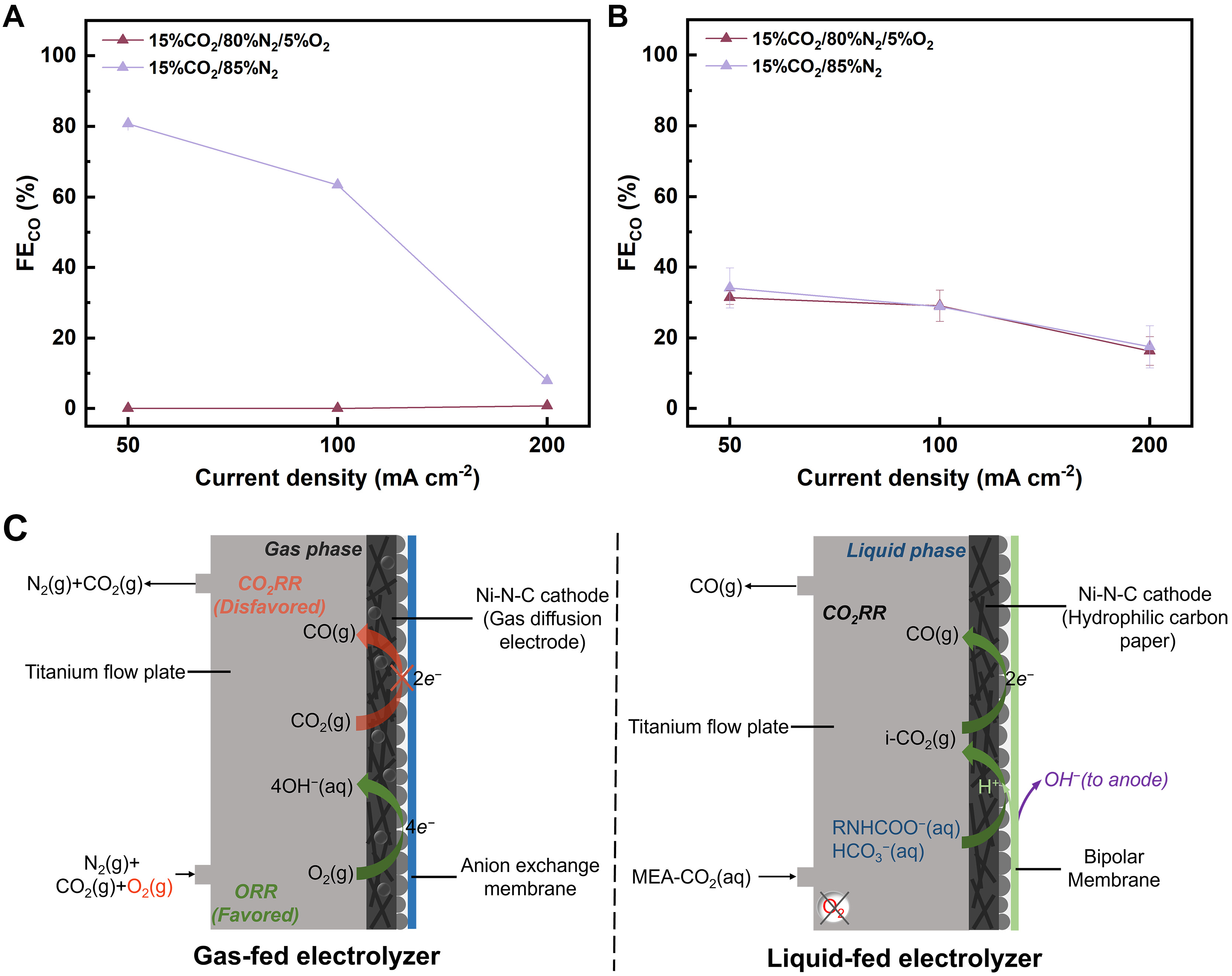
Figure 2. FECO recorded for electrolysis of (A) 15% CO2/80% N2/5% O2 and 15% CO2/85% N2 in the gas-fed electrolyzer and (B) CO2-capturing 5 M MEA under 15% CO2/80% N2/5% O2 and 15% CO2/85% N2 atmosphere in the liquid-fed electrolyzer. The error bars represent the standard deviation of two independent measurements; (C) Schematic diagrams of reaction processes in the cathodic chambers of the gas-fed and liquid-fed electrolyzers. FE: Faraday efficiencies; FECO: Faraday efficiency for CO; MEA: monoethanolamine; CO2RR: CO2 reduction reaction; ORR: oxygen reduction reaction.
In contrast, the cell voltage for the reduction current observed in CO2-capturing MEA solution under a gas mixture of 15% CO2/80% N2/5% O2 is quite similar to that under 15% CO2/85% N2 [Supplementary Figure 8]. The FECO is 31%, 29%, and 16% at 50, 100, and 200 mA·cm-2, respectively, which are similar to those recorded under O2-free conditions [Figure 2B and Supplementary Figure 9]. Notably, no obvious decrease in FECO is observed when the O2 concentration increases to 10%, 20%, or even 100% [Supplementary Figure 10]. To further quantify the oxygen effect, the dissolved oxygen concentration in the electrolyte is measured under 15% CO2/85% N2, 15% CO2/80% N2/5% O2, and 100% O2 conditions, with each gas continuously bubbled into the solution for 30 min [Supplementary Figure 11]. The dissolved oxygen concentration is 0.003 mM under 15% CO2/85% N2, 0.060 mM under 15% CO2/80% N2/5% O2, and 0.492 mM under 100% O2 after 30 min. Despite the large differences in dissolved oxygen concentration, the FECO in the liquid-fed system remains comparable across all tested conditions. This indicates that O2 in the flue gas stream has negligible influence on the electrochemical conversion of CO2-capturing MEA solution, making the system oxygen-tolerant.
Figure 2C illustrates the electrolysis process in the gas-fed and liquid-fed electrolyzers in the presence of O2. In the gas-fed electrolyzer, the ORR dominates over CO2 reduction due to its more favorable thermodynamics and comparable concentrations to CO2, thereby suppressing CO production, which aligns with previous studies[48,49]. However, the impact of O2 is negligible in the liquid-fed electrolyzer. In aqueous media, the solubility of O2 is only 0.0012 M (1 atm, 298 K), much lower than that of CO2 (0.034 M, 1 atm,
After validating the direct conversion of CO2-capturing MEA solution, we establish a concerted CO2 capture and conversion system by coupling a simple CO2 absorber with an electrolyzer designed for CO2-capturing MEA [Figure 3A]. To enhance both CO2 capture efficiency and CO production rate, the active area of the Ni-N-C electrode is increased to
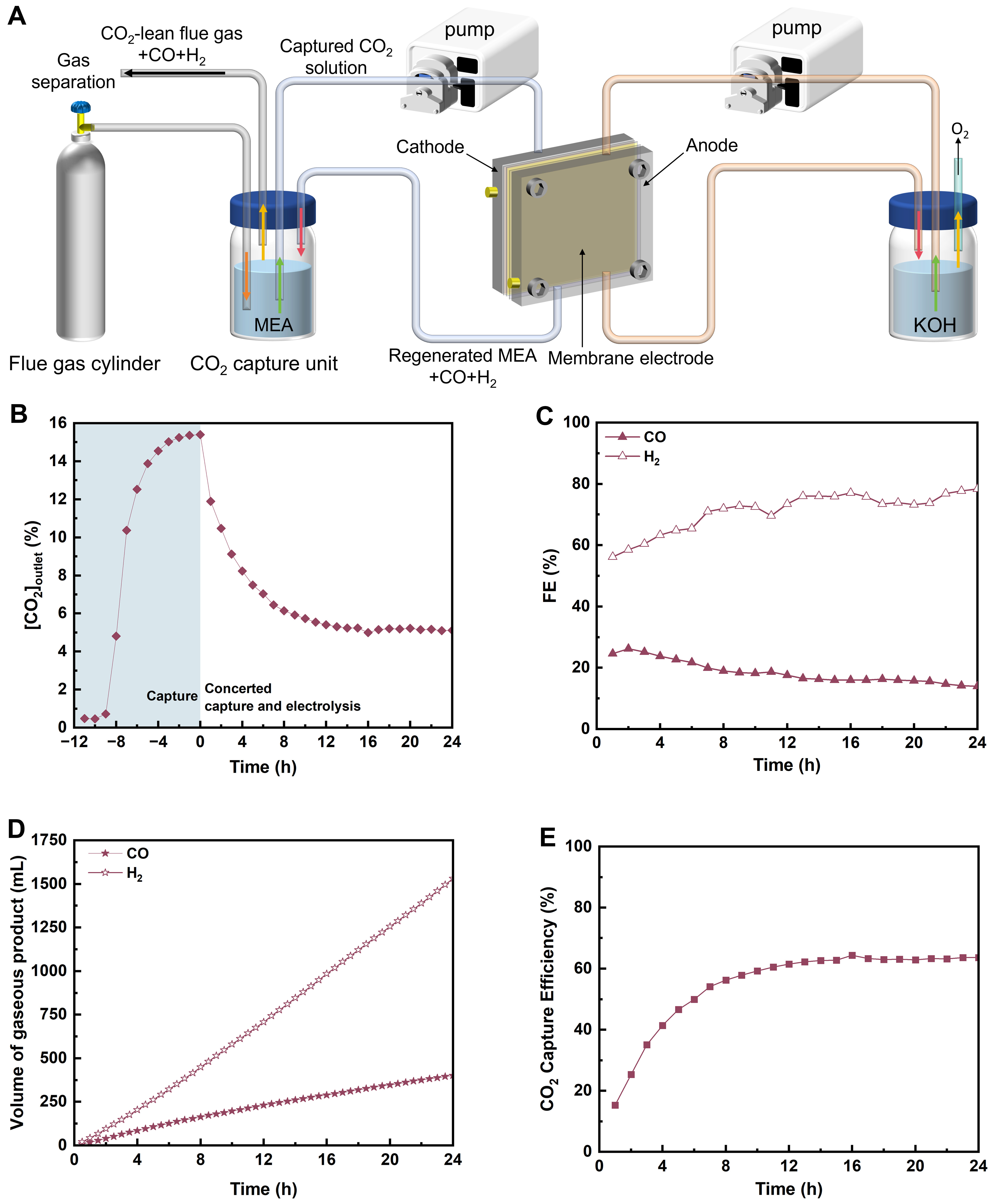
Figure 3. (A) Schematic illustration of a concerted CO2 capture and conversion system; (B-E) Efficiency of the concerted system using 2 M MEA to capture CO2 from a flue gas containing 15% CO2/80% N2/5% O2 and performing electrolysis of the CO2-capturing MEA at 50 mA·cm-2 for 24 h: (B) concentration of CO2 leaving the concerted system ([CO2]outlet); (C) FE for CO and H2; (D) cumulative volume of gaseous products; (E) CO2 capture efficiency. The shaded region in Figure 3B shows the CO2 concentration change in the outlet gas stream during 12 h CO2 capture from a simulated flue gas (15% CO2/80% N2/5% O2) using 2 M MEA. MEA: Monoethanolamine; FE: Faraday efficiencies.
The system achieves a maximum FECO of 26% after
To investigate the influence of reaction rate on the concerted CO2 capture and conversion system, the electrolysis is then carried out at a higher current density of 100 mA·cm-2 [Supplementary Figure 13]. However, a lower FECO of 20% is observed due to the intensified HER. Nevertheless, a higher CO2 capture efficiency of 73% is achieved compared to electrolysis at 50 mA·cm-2, which can be attributed to accelerated regeneration of MEA driven by the enhanced consumption of reactive carbon species at the higher electrolysis current density. This result shows that increasing the current density of electrolysis can improve CO2 capture efficiency, though it may reduce the efficiency of the subsequent conversion step. Therefore, a trade-off exists between the efficiencies of CO2 capture and electrochemical conversion.
To gain molecular-level insight into the electrode environment during this concerted process, we employed in situ ATR-FTIR spectroscopy to monitor the electrolysis of a 2 M MEA solution pre-saturated with the simulated flue gas (15% CO2/80% N2/5% O2). As shown in Figure 4, during potentiostatic electrolysis, a distinct decrease in the CO2 characteristic peak (2,362 cm-1) was observed, indicating CO2 consumption at the electrode surface[52,53]. Key solution species were identified by peaks at 1,567, 1,495, 1,390, and 1,330 cm-1, which were attributed to RNHCOO-[53]. The peak at 1,222 cm-1 corresponded to HCO3-[54], consistent with the NMR results [Supplementary Figure 2]. The presence of MEA-H+ (1,632-1,651 cm-1) was also confirmed, though this peak may overlap with water bending vibrations in the same range[52,55]. Notably, weak features associated with adsorbed CO intermediates (COL at
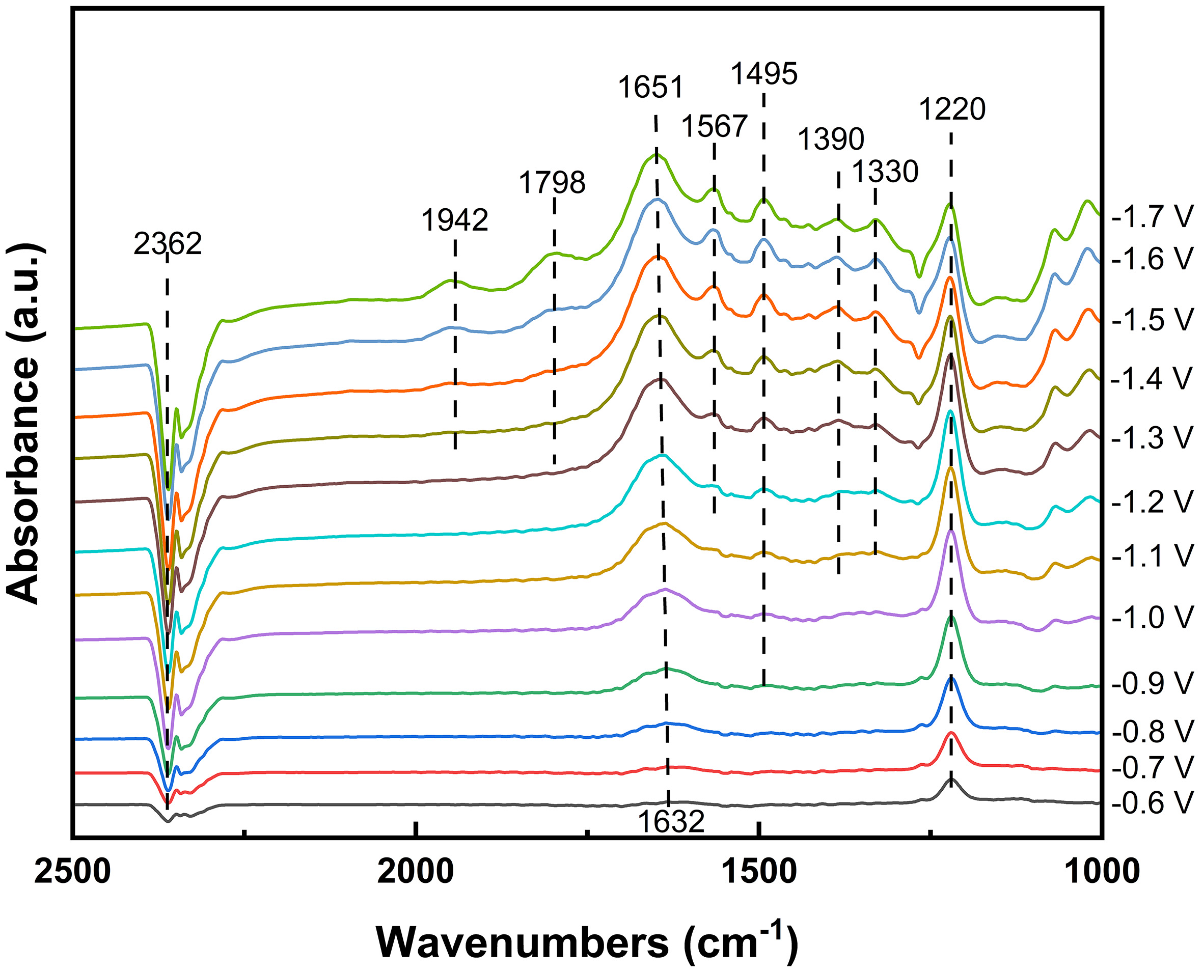
Figure 4. In situ ATR-FTIR spectra for electrolysis of 2 M MEA solution saturated with 15% CO2/5% O2/80% N2 flue gas at varying potentials under N2 atmosphere. ATR-FTIR: Attenuated total reflection Fourier transform infrared; MEA: monoethanolamine.
Building on this understanding of the electrode microenvironment, we sought to further enhance the CO2 conversion efficiency by modifying the electrode structure. We incorporated PTFE into the Ni-N-C catalyst to increase the hydrophobicity of the electrode surface, a feature that has been shown to suppress HER[57]. Using the same procedure as for the Ni-N-C electrode, 100 µL of 2 wt% PTFE solution was added to the catalyst ink to fabricate the Ni-N-C-PTFE electrode. CO2 capture and electrolysis were then carried out simultaneously by applying a constant current of 50 mA·cm-2 in 15% CO2-capturing MEA solution [Figure 5 and Supplementary Figure 14]. As shown in Figure 5A, the Ni-N-C-PTFE electrode exhibits a FECO of up to 32% within the first 2 h, surpassing the unmodified Ni-N-C electrode (FECO = 26%). Over the following 22 h, however, the FECO gradually declines, eventually reaching the same level in both cases. The corresponding CO2 capture efficiency remains stable at ~63%, consistent with that observed for the unmodified Ni-N-C cathode [Supplementary Figure 14B]. Encouragingly, the higher initial CO production rate with the PTFE-modified electrode results in a cumulative output of 432 mL CO and 1,381 mL H2, forming a syngas with a H2/CO = 3.2, lower than 3.8 for the unmodified electrode. The resulting syngas composition is suitable for Fischer-Tropsch synthesis to produce value-added liquid fuels, such as light olefins[58].
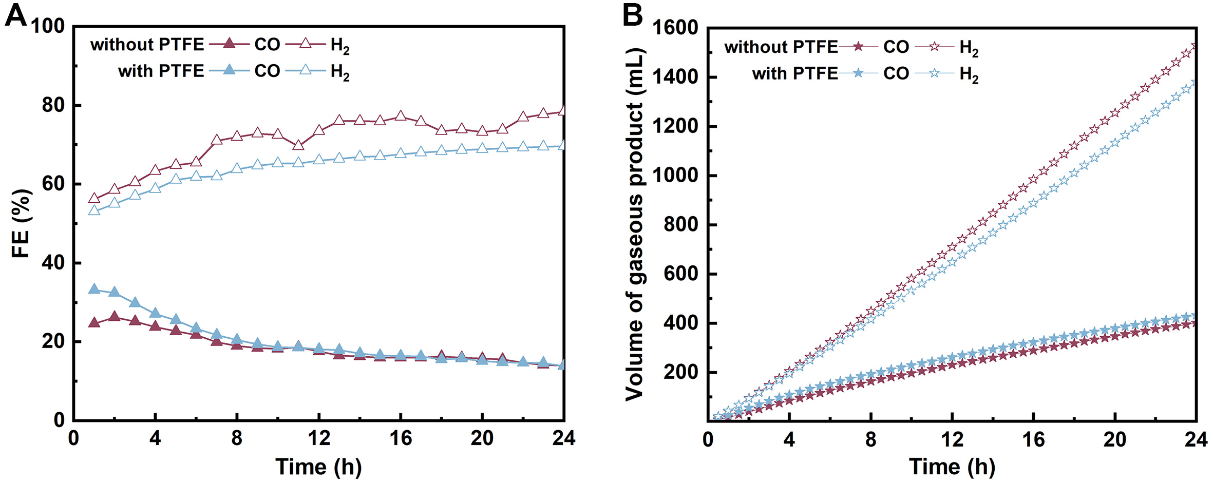
Figure 5. (A) FE and (B) cumulative volume of CO and H2 produced in the concerted CO2 capture and conversion system using 2 M MEA as the capture medium and conducting electrolysis at 50 mA·cm-2 under 15% CO2/80% N2/5% O2 with Ni-N-C and Ni-N-C-PTFE electrodes. FE: Faraday efficiencies; MEA: monoethanolamine; PTFE: polytetrafluoroethylene.
We also performed electrolysis of 15% CO2-capturing MEA under a N2 flow to examine the role of continuous CO2 supply. At the same current density (50 mA·cm-2), the [CO2]outlet is lower in the absence of CO2 feed than with the supply of 15% CO2 [Supplementary Figure 15A]. Consequently, FECO remains lower under N2 flow than under 15% CO2 throughout the 24 h of electrolysis. Notably, FECO declines to only 5% at the end of 24 h of electrolysis under N2 flow [Supplementary Figure 15B]. As a result, 269 mL CO and
Since the composition of flue gas varies in real-world scenarios, we then examine the influence of CO2 concentration in simulated flue gas on the efficiency of CO2 capture and subsequent conversion. To this end, the CO2 concentration is varied from 15% to 5% by diluting with N2 and O2. The resulting gas mixtures are continuously bubbled into 2 M MEA solutions at the same flow rate (50 sccm) to perform CO2 capture. Due to the lower CO2 concentration, CO2 capture requires an additional 10 h for flue gas containing 5% CO2 compared with its 15% CO2 counterpart, as evidenced by measurements of the CO2 concentration in the outlet gas and the pH of the MEA solution [Figure 6A and Supplementary Figure 16]. Notably, a higher steady-state pH is observed in the system supplied with 5% CO2, suggesting that a lower CO2 partial pressure reduces CO2 loading at the end of CO2 capture.
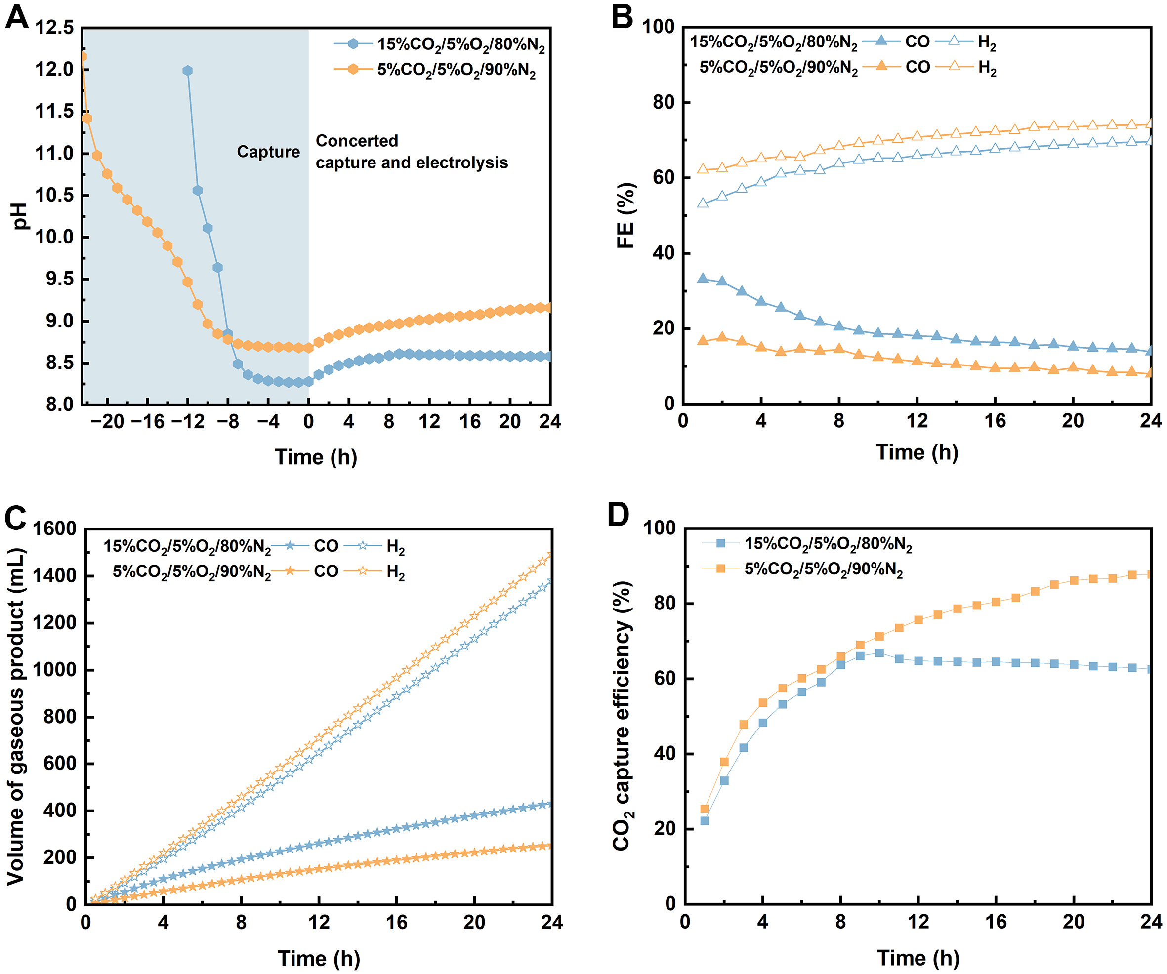
Figure 6. Efficiency of concerted CO2 capture and conversion system using 2 M MEA to capture CO2 from a flue gas containing 15% CO2/5% O2/80% N2 or 5% CO2/5% O2/90% N2 and conducting electrolysis of the CO2-capturing MEA at 50 mA·cm-2 for 24 h: (A) pH evolution during CO2 capture and subsequent conversion; (B) FE for CO and H2 production; (C) cumulative volume of CO and H2 products; (D) CO2 capture efficiency. The shaded region in Figure 6A shows the pH change in the solution during 12 and 24 h CO2 capture from simulated flue gases (15% CO2/80% N2/5% O2 and 5% CO2/90% N2/5% O2) using 2 M MEA. MEA: Monoethanolamine.
Similarly, concerted capture and electrochemical conversion of CO2 from flue gas containing 5% CO2 are performed using the Ni-N-C-PTFE electrode under the same conditions used for flue gas containing 15% CO2. As shown in Figure 6B and C, the FECO recorded in 5% CO2-capturing MEA solution is consistently lower than that in a 15% CO2-capturing MEA solution, resulting in the production of
Building on the above parameter optimization, we determined that CO2 capture from 15% CO2 by 2 M MEA and electrolysis at 50 mA·cm-2 with the Ni-N-C-PTFE electrode provides a favorable balance between CO2 capture efficiency and CO selectivity. To further elucidate the origin of this balance, we analyze the dynamic relationship between CO2 capture and electrolysis by calculating CO2 capture rate and CO production rate (the latter corresponding to the MEA regeneration rate), enabling a quantitative evaluation of their relationship during operation.
The reactions involved in CO2 capture and electrolysis processes are presented in Supplementary Equations 1-14 in Supplementary Figure 18. As shown in Supplementary Figure 19, the CO2 capture rate is very low initially. This is because the starting solution is a 15% CO2-capturing MEA solution, in which MEA predominantly exists as MEA-H+, carbamate, and HCO3- [Supplementary Equations 1-3], leaving negligible free MEA available for additional CO2 absorption. Upon electrolysis, several steps occur simultaneously. Water splitting occurs at the BPM of the membrane electrode assembly, generating H+ and OH- [Supplementary Equation 4]. In an ideal case, all H+ react with carbamate and bicarbonate species to release CO2 and partially regenerate MEA [Supplementary Equations 5 and 6]. The CO2 is then reduced to CO at the cathode, generating CO and OH- [Supplementary Equation 7]. The OH- can react with MEA-H+ [Supplementary Equation 8], regenerating MEA completely. At the anode, the OH- from water splitting is oxidized to generate O2 [Supplementary Equation 12]. Overall, the net reaction for CO2 capture and conversion is CO2 splitting [Supplementary Equation 13], which simultaneously depletes the captured CO2 species and regenerates MEA [Supplementary Equations 5-8]. However, the electrolysis system is very complicated. Some H+ from the BPM and MEA-H+ itself will be reduced directly to generate H2 [Supplementary Equations 10 and 11], competing with CO2 release and reduction steps. However, the overall reaction for H2 evolution will not regenerate MEA [Supplementary Equation 14]. In addition, some H+ will react with OH- generated during CO2 reduction, neutralizing the additionally generated OH- in the cathodic chamber [Supplementary Equation 9]. Therefore, the MEA regeneration rate would in principle be the same as the CO production rate.
As the concentration of free MEA increases, the solution progressively regains its capacity to capture CO2, leading to a continuous increase in the CO2 capture rate. Around 12 h, a dynamic balance between MEA regeneration by electrolysis and consumption by CO2 capture is established, and the capture rate approaches a steady state [Supplementary Figure 19].
In contrast, the CO production rate gradually decreases over time. This decline is primarily attributed to the increase in local pH near the cathode. Continuous CO2 reduction generates OH- [Supplementary Equation 7], which raises the electrode interfacial alkalinity and shifts the equilibrium away from free CO2 (toward carbonate/bicarbonate species). This shift makes CO2 release more difficult, thereby reducing the availability of molecular CO2 for electroreduction. In addition, prolonged operation may also induce catalyst surface changes and mass transport limitations, further contributing to the decrease in CO production rate.
Notably, the CO2 capture rate and CO production rate intersect at approximately 4.5 h [Supplementary Figure 19]. This crossover point represents a transient state where CO2 supply and consumption are momentarily balanced. However, due to the direct reduction of H+ from BPM [Supplementary Equation 10], the generated OH- from CO2 reduction cannot be immediately neutralized [Supplementary Equation 9], which can capture additional CO2. This indicates that the capture capacity of the catholyte has not yet been reached. As a result, the capture rate continues to rise beyond this point, while the CO production rate cannot be sustained due to the progressively unfavorable cathodic microenvironment. At a certain point (under the selected CO2 capture and electrolysis conditions for ~12 h), the balance for CO2 capture and electrolysis is reached.
These results demonstrate that the rate mismatch originates from the different temporal evolution of CO2 capture in the bulk solution versus CO2 conversion at the electrode. Importantly, this balance can be tuned by adjusting both CO2 supply (inlet CO2 concentration) and CO2 utilization (electrolysis current density), enabling optimal conditions under which CO2 capture efficiency and CO selectivity are simultaneously optimized.
Finally, the MEA-mediated concerted system is compared with both conventional sequential and recently reported carbonate-based concerted systems [Supplementary Table 1]. The comparison involves key metrics such as Faraday efficiency and partial current density for CO production, total current density, stability, CO2 capture efficiency, and energy consumption (Details of the energy consumption calculation are provided in Supplementary Note 1). We note that the Faraday efficiency and partial current density for CO production of our MEA-mediated system are currently lower than those of conventional sequential systems, yet comparable to recently reported carbonate-based concerted systems. Notably, our system offers an advantage in overall energy consumption compared to the conventional sequential route, as it eliminates the need for energy-intensive upstream CO2 desorption (e.g., thermal regeneration). Additionally, our system also exhibits a twofold higher CO2 capture efficiency compared to carbonate-based concerted systems, because of the faster CO2 absorption kinetics of amines. These results suggest that the MEA-mediated system enables effective CO2 capture and utilization.
CONCLUSIONS
We have developed an MEA-based system for concerted CO2 capture and electrochemical conversion by combining a simple CO2 absorber with a liquid-fed electrolyzer. The CO2-capturing MEA solution is directly utilized as the liquid feedstock for electrochemical conversion, enabling in situ CO2 release and subsequent syngas production over a Ni single-atom catalyst. The system shows strong tolerance to oxygen and is feasible for concerted CO2 capture and electrochemical conversion under flue gas conditions. Through optimization of current density, electrode hydrophobicity, and CO2 concentration, we achieved a high CO2 capture efficiency of 63% and efficiently produce syngas with H2/CO = 3.2. This work demonstrates the feasibility of MEA-mediated concerted CO2 capture-conversion for flue gas upgrading, while further optimizations in amine structure, catalyst stability, electrode design, and system operation are warranted for long-term applications.
DECLARATIONS
Authors’ contributions
Performed research and analyzed data: Yin, C. Q.
Assisted with the electrolysis and data analysis: Zou, Y. B.; Lv, Z. H.
Conceived and supervised the research: Li, Y.; Hu, X. M.
Wrote and revised the manuscript: Yin, C. Q.; Du, L.; Li, Y.; Hu, X. M.
Availability of data and materials
The data that support the findings of this study are available from the corresponding author upon reasonable request.
AI and AI-assisted tools statement
Not applicable.
Financial support and sponsorship
This work was financially supported by National Natural Science Foundation of China (Nos. 22509114, and 22376120), Taishan Scholars program from Shandong Province (Nos. tsqn202103021, and tsqn202507032), and Shandong Provincial Natural Science Foundation (No. ZR2025QC1317).
Conflicts of interest
All authors declared that there are no conflicts of interest.
Ethical approval and consent to participate
Not applicable.
Consent for publication
Not applicable.
Copyright
© The Author(s) 2026.
Supplementary Materials
REFERENCES
1. Babila, T. L.; Penman, D. E.; Standish, C. D.; et al. Surface ocean warming and acidification driven by rapid carbon release precedes Paleocene-Eocene Thermal Maximum. Sci. Adv. 2022, 8, eabg1025.
2. Huang, M.; Reich, P. B.; Wang, S.; et al. Nitrogen and CO2 enrichment interact to decrease biodiversity impact on complementarity and selection effects. Nat. Commun. 2025, 16, 7445.
3. Garg, S.; Biswas, A. N.; Chen, J. G. Opportunities for CO2 upgrading to C3 oxygenates using tandem electrocatalytic-thermocatalytic processes. Carbon. Future. 2024, 1, 9200002.
4. Allangawi, A.; Xiao, X. T.; Ma, X.; et al. Selective electrocatalytic CO2 reduction to methanol: a roadmap toward practical implementation. Angew. Chem. Int. Ed. 2025, 64, e202517916.
5. Zou, J.; Gupta, D.; Liang, G. CO2 utilization in energy storage and conversion. J. Mater. Chem. A. 2025, 13, 32004-29.
6. Chen, C.; Kosari, M.; Jiang, Z.; et al. Boosting CO2 hydrogenation to methanol via enriching the Cu–ZnO interface on layered double oxides. Small 2025, 21, 2412786.
7. De La Torre, P.; An, L.; Chang, C. J. Porosity as a design element for developing catalytic molecular materials for electrochemical and photochemical carbon dioxide reduction. Adv. Mater. 2023, 35, 2302122.
8. Patil, O. U.; Park, S. Recent progress of the electrocatalytic CO2 reduction reaction using porous materials. Chem. Commun. 2025, 61, 9531-42.
9. Nzotcha, U.; Sanz, S.; Tempel, H.; Eichel, R. A. Technoeconomic perspective on the electroreduction of CO2 to formic acid: scale-up strategies toward industrial viability. Angew. Chem. Int. Ed. 2025, 64, e202418114.
10. Sun, Q.; Jia, C.; Lu, H.; et al. Ampere-level electroreduction of CO2 and CO. Chem. Soc. Rev. 2025, 54, 6973-7016.
11. Pimlott, D. J. D.; Jewlal, A.; Kim, Y.; Berlinguette, C. P. Oxygen-resistant CO2 reduction enabled by electrolysis of liquid feedstocks. J. Am. Chem. Soc. 2023, 145, 25933-7.
12. Harvey, C. M.; Chardon-noblat, S.; Costentin, C. Self-protection mechanism and mass transport governing O2 tolerance in an iron porphyrin homogeneous catalyst for CO2 electroreduction. J. Am. Chem. Soc. 2025, 147, 24171-8.
13. Cheng, Y.; Hou, P.; Wang, X.; Kang, P. CO2 electrolysis system under industrially relevant conditions. Acc. Chem. Res. 2022, 55, 231-40.
14. Xie, L.; Cai, Y.; Jiang, Y.; et al. Direct low concentration CO2 electroreduction to multicarbon products via rate-determining step tuning. Nat. Commun. 2024, 15, 10386.
15. Gao, W.; Liang, S.; Wang, R.; et al. Industrial carbon dioxide capture and utilization: state of the art and future challenges. Chem. Soc. Rev. 2020, 49, 8584-686.
16. Zhang, S.; Tang, W.; Yin, J.; et al. Feasibility and prospects of electrocatalytic conversion of CO2 for chemical feedstock production and renewable energy storage. ACS. Sustainable. Chem. Eng. 2025, 13, 9841-58.
17. Elgazzar, A.; Zhu, P.; Chen, F.; et al. Electrochemical CO2 reduction to formic acid with high carbon efficiency. ACS. Energy. Lett. 2024, 10, 450-8.
18. Belsa, B.; Xia, L.; García De Arquer, F. P. CO2 electrolysis technologies: bridging the gap toward scale-up and commercialization. ACS. Energy. Lett. 2024, 9, 4293-305.
19. Osorio-tejada, J.; Escriba-gelonch, M.; Vertongen, R.; Bogaerts, A.; Hessel, V. CO2 conversion to CO via plasma and electrolysis: a techno-economic and energy cost analysis. Energy. Environ. Sci. 2024, 17, 5833-53.
20. Deng, W.; Lee, A.; Dai, W.; et al. Techno-economics of polymer-membrane-based CO2 electrolysers. Nat. Rev. Clean. Technol. 2025, 1, 255-68.
21. Yulia, F.; Sofianita, R.; Prayogo, K.; Nasruddin, N. Optimization of post combustion CO2 absorption system monoethanolamine (MEA) based for 320 MW coal-fired power plant application - exergy and exergoenvironmental analysis. Case. Stud. Therm. Eng. 2021, 26, 101093.
22. Fytianos, G.; Grimstvedt, A.; Knuutila, H.; Svendsen, H. F. Effect of MEA’s degradation products on corrosion at CO2 capture plants. Energy. Procedia. 2014, 63, 1869-75.
23. Vevelstad, S. J.; Buvik, V.; Knuutila, H. K.; Grimstvedt, A.; Da Silva, E. F. Important aspects regarding the chemical stability of aqueous amine solvents for CO2 capture. Ind. Eng. Chem. Res. 2022, 61, 15737-53.
24. Namdari, M.; Kim, Y.; Pimlott, D. J. D.; Jewlal, A. M. L.; Berlinguette, C. P. Reactive carbon capture using electrochemical reactors. Chem. Soc. Rev. 2025, 54, 590-600.
25. Zhang, Z.; Lees, E. W.; Habibzadeh, F.; et al. Porous metal electrodes enable efficient electrolysis of carbon capture solutions. Energy. Environ. Sci. 2022, 15, 705-13.
26. Song, H.; Fernández, C. A.; Choi, H.; Huang, P.; Oh, J.; Hatzell, M. C. Integrated carbon capture and CO production from bicarbonates through bipolar membrane electrolysis. Energy. Environ. Sci. 2024, 17, 3570-9.
27. Leverick, G.; Bernhardt, E. M.; Ismail, A. I.; et al. Uncovering the active species in amine-mediated CO2 reduction to CO on Ag. ACS. Catal. 2023, 13, 12322-37.
28. Zou, Y.; Zheng, A.; Feng, L.; Du, L.; Daasbjerg, K.; Hu, X. Integrated capture and electrochemical conversion of CO2 from flue gas mediated by carbonate/bicarbonate cycle. J. Mater. Chem. A. 2025, 13, 36191-201.
29. Pimlott, D. J. D.; Kim, Y.; Berlinguette, C. P. Reactive carbon capture enables CO2 electrolysis with liquid feedstocks. Acc. Chem. Res. 2024, 57, 1007-18.
30. Jewlal, A. M. L.; Kim, Y.; Crescenzo, G. V.; Berlinguette, C. P. Go with CO: a case for targeting carbon monoxide as a reactive carbon capture product. ACS. Energy. Lett. 2025, 10, 2498-502.
31. Kim, Y.; Lees, E. W.; Donde, C.; et al. Integrated CO2 capture and conversion to form syngas. Joule 2024, 8, 3106-25.
32. Cai, T.; Johnson, J. K.; Wu, Y.; Chen, X. Toward understanding the kinetics of CO2 capture on sodium carbonate. ACS. Appl. Mater. Interfaces. 2019, 11, 9033-41.
33. Wang, T.; Yu, W.; Fang, M.; et al. Wetted-wall column study on CO2 absorption kinetics enhancement by additive of nanoparticles. Greenhouse. Gases. Sci. Technol. 2015, 5, 682-94.
34. Krótki, A.; Więcław Solny, L.; Stec, M.; et al. Experimental results of advanced technological modifications for a CO2 capture process using amine scrubbing. Int. J. Greenh. Gas. Con. 2020, 96, 103014.
35. Feng, L.; Lv, Z.; Kong, Y.; Hu, X. Upcycling of plastic waste to atomic nickel site-decorated carbon for efficient electrochemical CO2 conversion. Sustain. Energy. Fuels. 2024, 8, 2860-8.
36. Li, Y. C.; Lee, G.; Yuan, T.; et al. CO2 electroreduction from carbonate electrolyte. ACS. Energy. Lett. 2019, 4, 1427-31.
37. Mezzavilla, S.; Horch, S.; Stephens, I. E. L.; Seger, B.; Chorkendorff, I. Structure sensitivity in the electrocatalytic reduction of CO2 with gold catalysts. Angew. Chem. Int. Ed. 2019, 58, 3774-8.
38. Ko, Y. J.; Lim, C.; Jin, J.; et al. Extrinsic hydrophobicity-controlled silver nanoparticles as efficient and stable catalysts for CO2 electrolysis. Nat. Commun. 2024, 15, 3356.
39. Wang, M.; Torbensen, K.; Salvatore, D.; et al. CO2 electrochemical catalytic reduction with a highly active cobalt phthalocyanine. Nat. Commun. 2019, 10, 3602.
40. Wu, X.; Zhao, J. Y.; Sun, J. W.; et al. Isolation of highly reactive cobalt phthalocyanine via electrochemical activation for enhanced CO2 reduction reaction. Small 2023, 19, 2207037.
41. Karapinar, D.; Huan, N. T.; Ranjbar Sahraie, N.; et al. Electroreduction of CO2 on single-site copper-nitrogen-doped carbon material: selective formation of ethanol and reversible restructuration of the metal sites. Angew. Chem. Int. Ed. 2019, 58, 15098-103.
42. Paul, S.; Kao, Y.; Ni, L.; et al. Influence of the metal center in M-N-C catalysts on the CO2 reduction reaction on gas diffusion electrodes. ACS. Catal. 2021, 11, 5850-64.
43. Varela, A. S.; Ju, W.; Bagger, A.; Franco, P.; Rossmeisl, J.; Strasser, P. Electrochemical reduction of CO2 on metal-nitrogen-doped carbon catalysts. ACS. Catal. 2019, 9, 7270-84.
44. Li, Y.; Lu, X. F.; Xi, S.; Luan, D.; Wang, X.; Lou, X. W. Synthesis of N-doped highly graphitic carbon urchin-like hollow structures loaded with single-Ni atoms towards efficient CO2 electroreduction. Angew. Chem. Int. Ed. 2022, 61, e202201491.
45. Wang, J.; Huang, Y.; Wang, Y.; et al. Atomically dispersed metal-nitrogen-carbon catalysts with d-orbital electronic configuration-dependent selectivity for electrochemical CO2-to-CO reduction. ACS. Catal. 2023, 13, 2374-85.
46. Wang, H.; Liu, G.; Chen, C.; et al. Single-Ni sites embedded in multilayer nitrogen-doped graphene derived from amino-functionalized MOF for highly selective CO2 electroreduction. ACS. Sustainable. Chem. Eng. 2021, 9, 3792-801.
47. Wattanaphan, P.; Sema, T.; Idem, R.; Liang, Z.; Tontiwachwuthikul, P. Effects of flue gas composition on carbon steel (1020) corrosion in MEA-based CO2 capture process. Int. J. Greenh. Gas. Con. 2013, 19, 340-9.
48. Xu, Y.; Edwards, J. P.; Zhong, J.; et al. Oxygen-tolerant electroproduction of C2 products from simulated flue gas. Energy. Environ. Sci. 2020, 13, 554-61.
49. Li, P.; Lu, X.; Wu, Z.; et al. Acid-base interaction enhancing oxygen tolerance in electrocatalytic carbon dioxide reduction. Angew. Chem. Int. Ed. Engl. 2020, 59, 10918-23.
50. Weiss, R. Carbon dioxide in water and seawater: the solubility of a non-ideal gas. Mar. Chem. 1974, 2, 203-15.
51. Wei, X, Yin, G., Zhang, J., Eds. Rotating Electrode Methods and Oxygen Reduction Electrocatalysts; Elsevier, 2014.
52. Bruggeman, D. F.; Rothenberg, G.; Garcia, A. C. Investigating proton shuttling and electrochemical mechanisms of amines in integrated CO2 capture and utilization. Nat. Commun. 2024, 15, 9207.
53. Li, P.; Mao, Y.; Shin, H.; et al. Tandem amine scrubbing and CO2 electrolysis via direct piperazine carbamate reduction. Nat. Energy. 2025, 10, 1262-73.
54. Coenen, K.; Gallucci, F.; Mezari, B.; Hensen, E.; Van Sint Annaland, M. An in-situ IR study on the adsorption of CO2 and H2O on hydrotalcites. J. CO2. Util. 2018, 24, 228-39.
55. Mei, Z.; He, Y.; Liu, K.; et al. Enhanced *COOH adsorption over edge-rich Ni–N4 sites for efficient acidic CO2 electroreduction. J. Am. Chem. Soc. 2025, 147, 34101-8.
56. Dunwell, M.; Yan, Y.; Xu, B. In situ infrared spectroscopic investigations of pyridine-mediated CO2 reduction on Pt electrocatalysts. ACS. Catal. 2017, 7, 5410-9.
57. Liang, H.; Zhao, S.; Hu, X.; Ceccato, M.; Skrydstrup, T.; Daasbjerg, K. Hydrophobic copper interfaces boost electroreduction of carbon dioxide to ethylene in water. ACS. Catal. 2021, 11, 958-66.
Cite This Article
How to Cite
Download Citation
Export Citation File:
Type of Import
Tips on Downloading Citation
Citation Manager File Format
Type of Import
Direct Import: When the Direct Import option is selected (the default state), a dialogue box will give you the option to Save or Open the downloaded citation data. Choosing Open will either launch your citation manager or give you a choice of applications with which to use the metadata. The Save option saves the file locally for later use.
Indirect Import: When the Indirect Import option is selected, the metadata is displayed and may be copied and pasted as needed.
About This Article
Copyright

Data & Comments
Data
0


Comments
Comments must be written in English. Spam, offensive content, impersonation, and private information will not be permitted. If any comment is reported and identified as inappropriate content by OAE staff, the comment will be removed without notice. If you have any queries or need any help, please contact us at support@oaepublish.com.