


fig5
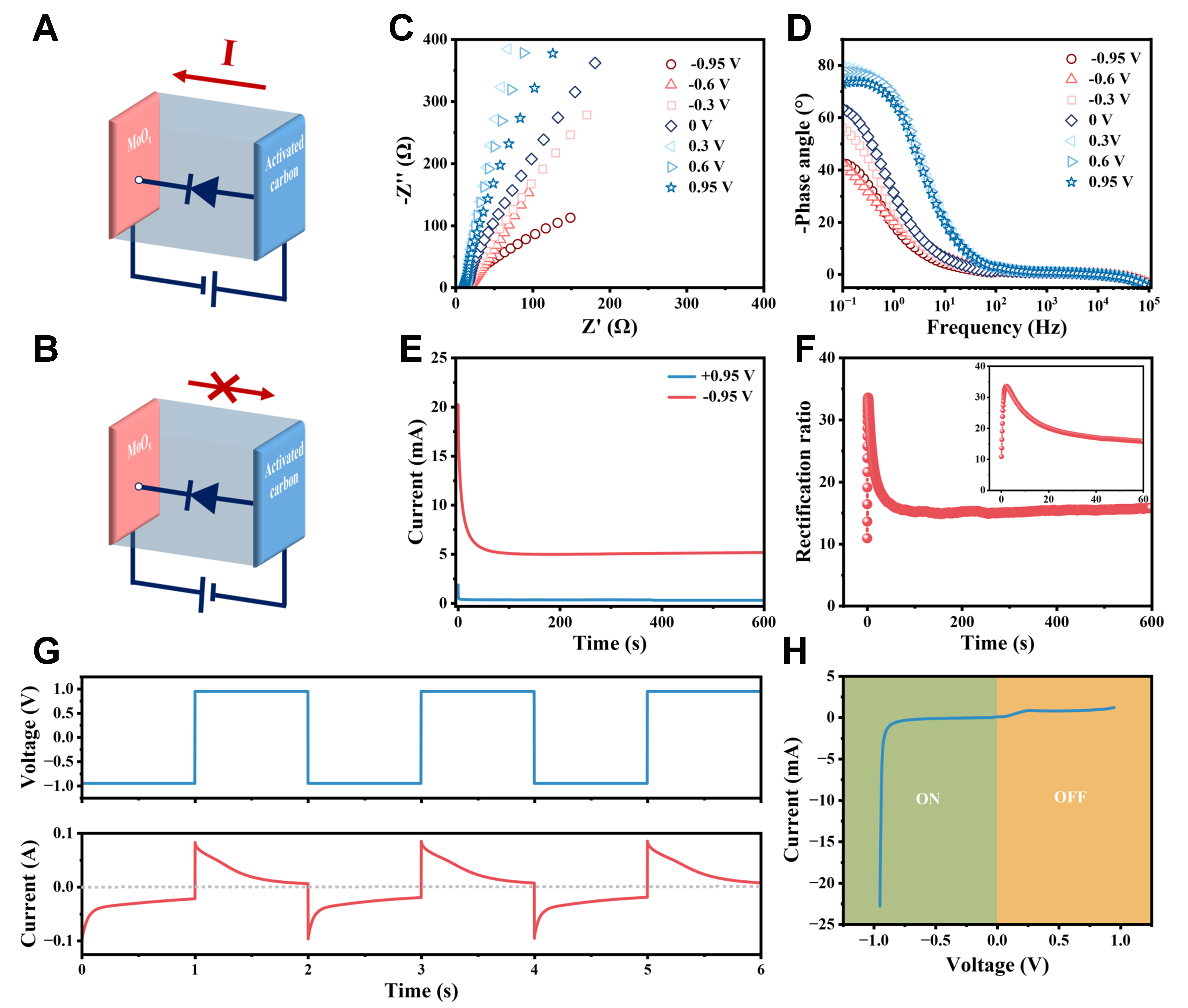
Figure 5. Rectification characteristics of a single CAPode. (A and B) Equivalent circuit diagrams of forward conduction (A) and reverse cutoff (B); (C and D) Nyquist plots (C) and Bode phase plots (D) of CAPode under different biases; (E and F) CA curves of CAPode under the bias voltages of ± 0.95 V (E) and the calculated rectification ratio to the bias application time (F); (G) CA curves of CAPode under alternating voltages of ± 0.95 V, applied for 1s; (H) I-V curve of CAPode. CA: Chronoamperometry; I-V: current-voltage.


