

fig12
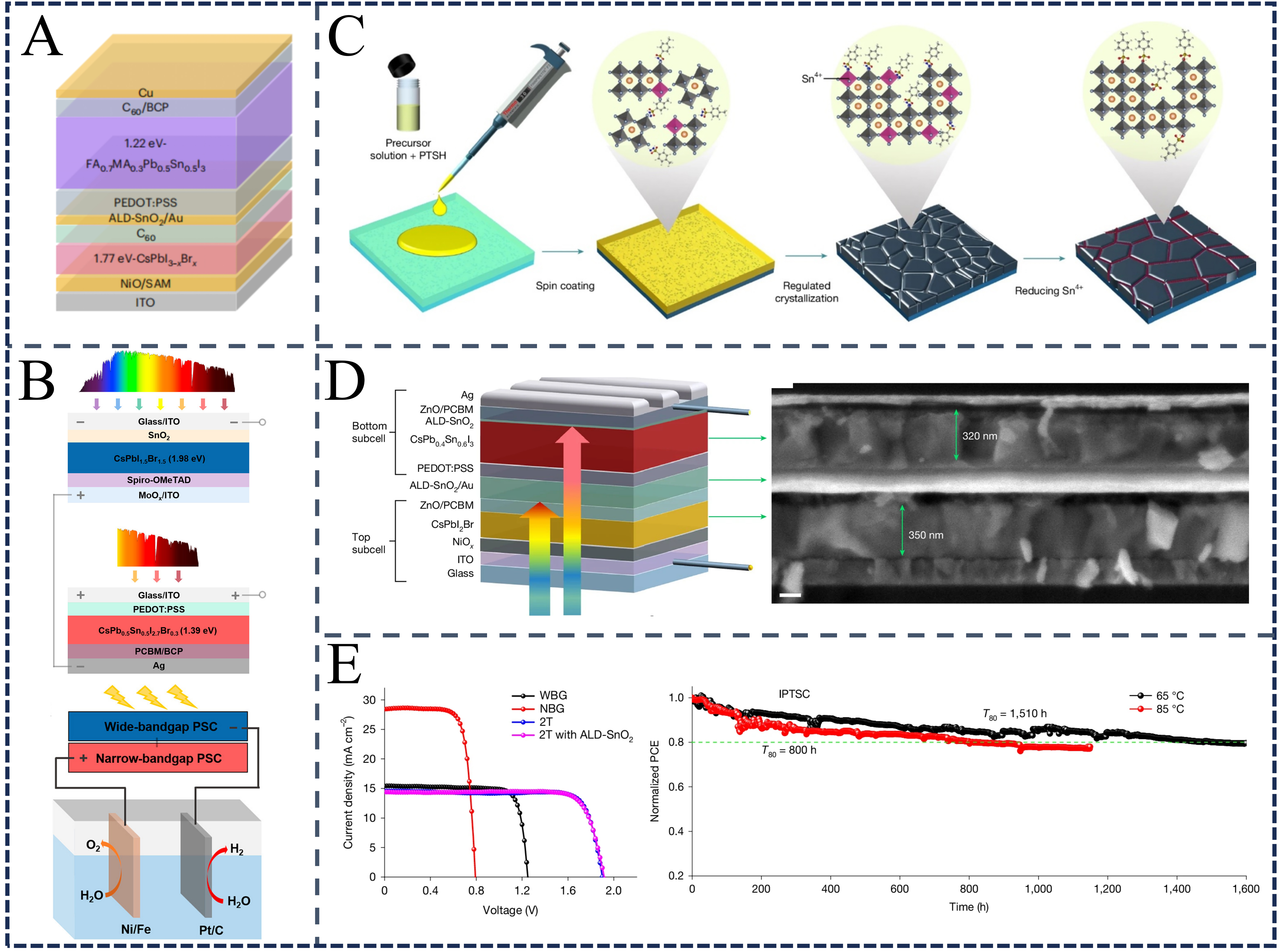
Figure 12. (A) Schematic structure of FA0.7MA0.3Pb0.5Sn0.5I3/CsPbI3-xBrx all-perovskite TSCs. This figure is quoted with permission from Ref.[209], Copyright © 2023 Springer Nature; (B) The schematic diagram of the Integrated 4T inorganic perovskite TSC and the solar water splitting system driven by the integrated 4T inorganic perovskite TSC. This figure is quoted with permission from Ref.[210], Copyright © 2022 American Chemical Society; (C) Schematic diagram of ligand evolution strategy; (D) 2T inorganic perovskite TSC structure diagram; (E) J-V curve and stability of 2T inorganic perovskite TSC. (C-E) are quoted with permission from Ref.[20], Copyright © 2025 Springer Nature. 2T: Two-terminal; 4T: four-terminal; ALD: atomic layer deposition; BCP: bathocuproine; FA: formamidinium; ITO: indium tin oxide; MA: methylammonium; NBG: narrow-bandgap; PCBM: phenyl-C61-butyric acid methyl ester; PEDOT:PSS: poly(3,4-ethylenedioxythiophene):poly(styrene sulfonate); PCE: power conversion efficiency; PSC: perovskite solar cell; PTSH: p-toluenesulfonyl hydrazide; SAM: self-assembled monolayer; TSCs: tandem solar cells; WBG: wide-bandgap.

