



fig1
From: Residual stress mapping of additively manufactured Inconel 718 via synchrotron X-ray diffraction
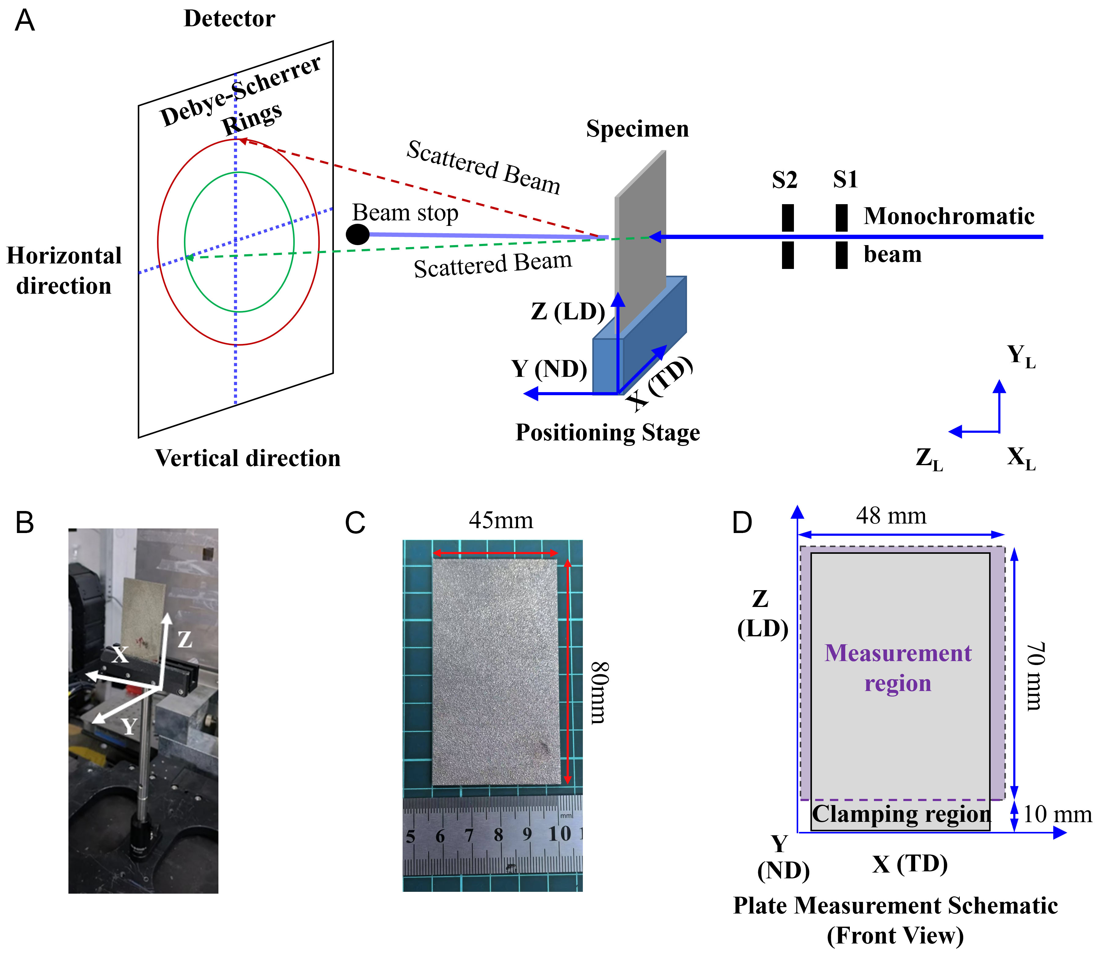
Figure 1. Schematic diagrams and experimental setup of residual stress measurement using synchrotron X-ray diffraction. (A) Schematic of the synchrotron experimental setup, showing the (X, Y, Z) and (XL, YL, ZL) coordinate systems used to define sample measurement and beamline locations, respectively; (B) photograph of the sample stage at the beamline, showing the sample mounted on the translation stage; (C) photograph of the as-built sample, indicating sample dimensions; (D) schematic diagram of the sample measurement, showing the sample coordinate directions and indicating the measurement and clamping regions. LD: Loading direction; TD: transverse direction; ND: normal direction.