


Controllable dielectric elastomer actuators for centimeter-scale flexible underwater robot
 0
0 Abstract
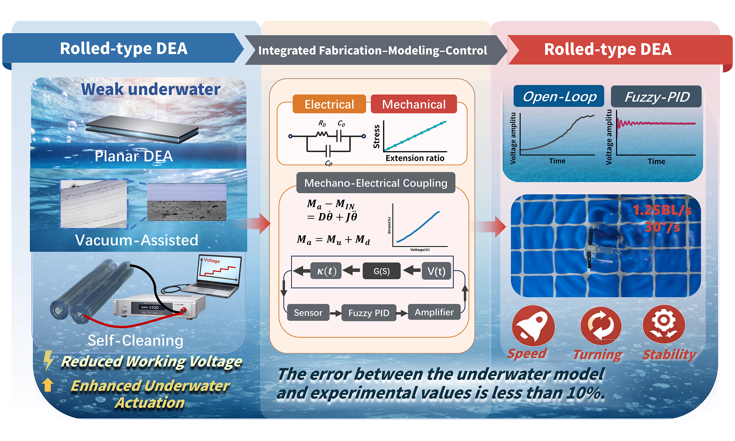
Traditional rigid underwater vehicles are often bulky and exhibit poor maneuverability, which limits their deployment in complex marine environments. In contrast, bio-inspired soft robotic fish are capable of mimicking efficient aquatic propulsion, while maintaining a compact structure and enhancing interaction safety. They demonstrate significant potential for marine sensing and exploration. Despite these advantages, reliable underwater locomotion control for dielectric elastomer actuators (DEAs) driven systems remains highly challenging because of large nonlinear deformations, time-varying parameters, and strong hydrodynamic damping. As a result, most existing prototypes still operate primarily in open loop. In this study, we develop a centimeter-scale manta ray-inspired robotic fish actuated by underwater-compatible rolled-type DEAs. Systematic underwater experiments are conducted, including speed regulation and turning performance tests. To attain stable and reliable underwater control, an experimentally calibrated voltage-curvature relationship for the rolled-type DEAs is established, and an underwater input-output model for reciprocating actuation is identified. These two factors jointly facilitate the implementation of a fuzzy proportional-integral-derivative (PID) closed-loop controller. Compared with open-loop operation, the closed-loop system improves disturbance rejection and dynamic response, resulting in more consistent swimming performance and maneuvering control. These results offer a practical approach for integrating the fabrication of DEAs, underwater integration, and closed-loop control, and contribute to the advancement of highly maneuverable centimeter-scale soft underwater robots.
Keywords
INTRODUCTION
Compared to traditional propeller-driven autonomous underwater vehicles (AUVs), bionic robotic fish demonstrate superior maneuverability, minimal operational noise, ultra-low energy consumption, and improved environmental compatibility[1]. They have been applied in the field of marine perception and achieved remarkable results, propelling the development of underwater robots towards greater depths, higher speeds, and enhanced autonomy[2]. Meanwhile, to guarantee the reliability and practical performance of underwater robots in complex marine environments, numerous technical challenges still need to be tackled[3], aiming to comprehensively explore the ocean and rationally exploit unexploited resources[4].
Underwater robotic fish can be classified according to their propulsion methods into two types: body/caudal fin (BCF) propulsion and median/paired fin (MPF) propulsion. A representative underwater robot using the BCF propulsion mode is the bionic Tunabot, which has a body length of 255 mm and a maximum swimming speed of up to 4 body lengths per second (BL/s)[5]. A typical example of the MPF propulsion mode is Galatea, a bionic underwater robot propelled by undulating fins[6]. Regarding the structural stiffness, robotic fish can be divided into three categories: fully rigid, rigid-flexible combined[7,8], and fully flexible[9]. However, these robotic fish either still have rigid components or a relatively large volume, resulting in drawbacks such as poor ecological compatibility and difficulty operating in narrow underwater scenarios. Therefore, research on fully flexible, centimeter-scale underwater robots has urgent practical significance[10-19].
Regarding the small-scale flexible underwater robots, researchers have put forward various solutions[20-22], which typically imitate the movement patterns of natural fish and utilize driving materials such as ionic polymer metal composites (IPMC)[23-26], shape memory alloys (SMA)[27-30], and piezoelectric materials (PZT)[31]. Dielectric elastomer (DE), one of the most promising functional materials for soft actuators, has been employed to build a soft electroactive structure for a robotic fish, which can achieve a swimming speed of up to 6.4 cm/s (0.69 BL/s) and operate for 3 h on a single charge[32]. Although there is a relatively large amount of research on flexible underwater robots, the high degree of freedom offered by flexible materials renders rigid modeling methods inapplicable. However, robust underwater closed-loop demonstrations for small-scale soft robotic fish remain limited, partly due to strong hydrodynamic damping and actuator nonlinearity[33].
Some researchers have characterized the constitutive equations of the device by formulating the mechanical model of a bionic fish tail[34]. In other works, the flexible device is simplified as a cantilever beam to deduce its deflection and bending moment[35]. Although the above approaches exhibit good engineering feasibility, they may not explicitly capture electromechanical coupling and large-deformation effects, which can limit accuracy and robustness under high-damping underwater conditions. Additionally, some researchers utilize neural networks to approximate the nonlinear dynamics of flexible devices and achieve online parameter adjustment. This model shows small prediction errors but is highly reliant on offline calibration or a substantial amount of training data[36].
To address these challenges, this study presents an integrated “fabrication-modeling-control” workflow for rolled-type dielectric elastomer actuators (DEAs) for centimeter-scale underwater robots. The workflow links fabrication, underwater integration, and closed-loop validation under strong hydrodynamic damping. Initially, the electromechanical models of rolled-type DEAs were constructed by employing extensively utilized formulations. Specifically, a parasitic capacitance was incorporated, and a second-order lumped RC (R: Resistor; C: Capacitor) representation (developed based on the first-order RC model) was adopted. Concurrently, a five-parameter Mooney-Rivlin mechanical model was utilized to parameterize the electromechanical behavior of the rolled-type DEAs. An empirical structural scaling factor of 0.75 was additionally introduced to address non-idealities during rolling and fabrication, thereby reducing the experimental error in bending characterization to less than 10%. Based on the experimentally determined input-output behavior, a well-established fuzzy-tuned proportional-integral-derivative (PID) strategy was applied in the high-damping underwater environment. The PID gains were adjusted online in accordance with the real-time error and its rate to enhance disturbance rejection. We then applied this integrated workflow to a centimeter-scale manta-ray-inspired underwater robot [Figure 1], and the prototype achieves controllable forward swimming, turning, and ascending motions. Compared with existing flexible robots[37-41], this robotic fish exhibits competitive maneuverability performance [Table 1]. It supports trajectory control in complex marine environments with improved mobility and reliability, facilitating more flexible and efficient underwater operations.
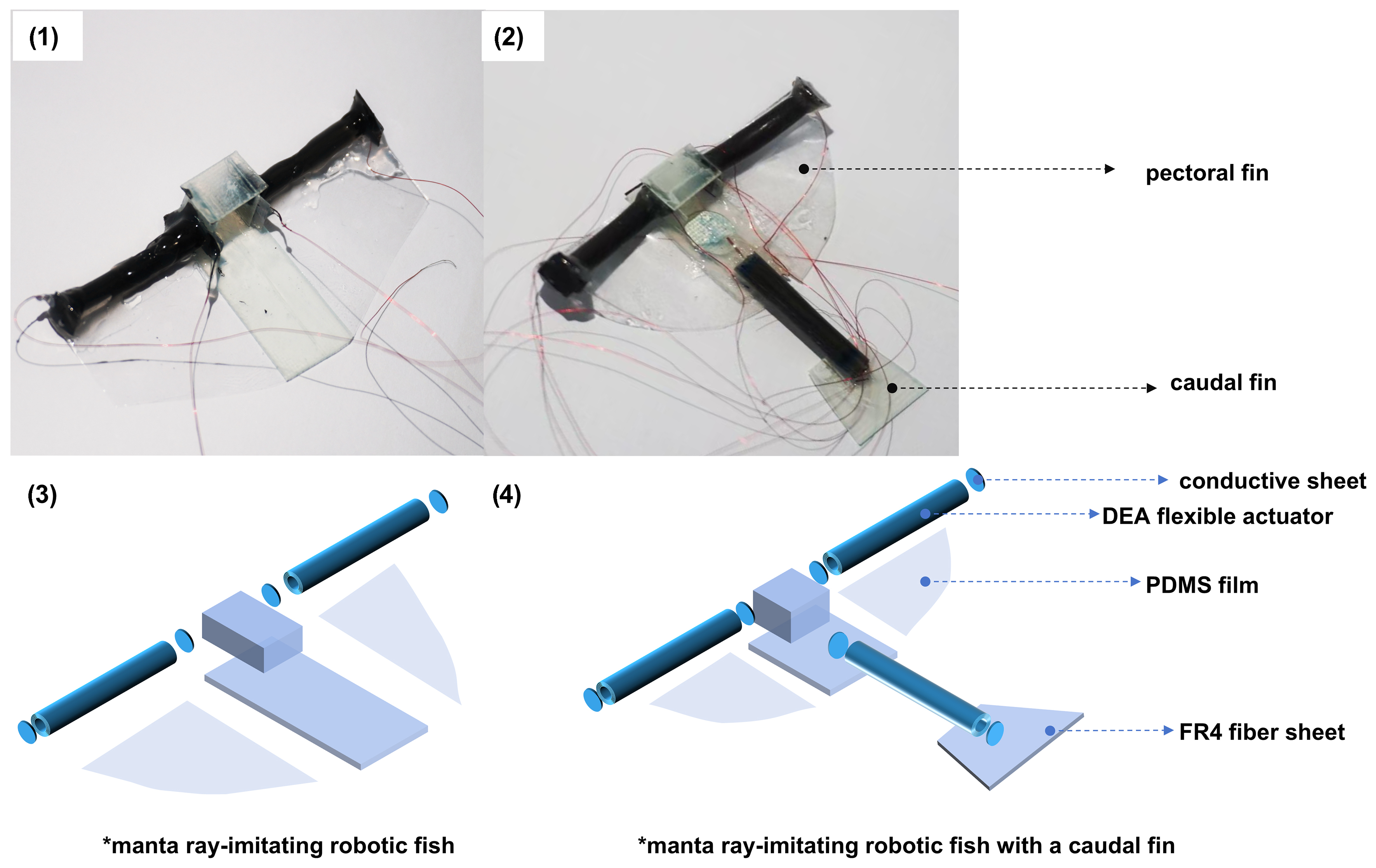
Figure 1. Prototype and schematic diagram of the manta-ray-inspired underwater robot. Photograph taken by the authors [Figure 1 (1) and Figure 1 (2)]. DEA: Dielectric elastomer actuator; PDMS: polydimethylsiloxane.
Comparison between the present work and existing robotic fish systems
| Ref. | Actuator/drive | Body length (mm) | Working voltage (kV) | Max speed (BL/s) | Turning rate (°/s) | Closed-loop control |
| This work | Rolled-type DEA | 30 | 0.5 | 1.25 | 30.0 | Yes |
| [37] | Jelly-like DEA | 30.3 | 6 (up to 7.0) | 0.3 | N/A | No |
| [38] | Pneumatic | N/A | N/A | 6.8 | N/A | No |
| [39] | DEA | 120 | 3.0 | 0.067 | N/A | No |
| [40] | Motor-driven | 240 | N/A | 0.18 | N/A | No |
| [41] | McKibben | ~211 | N/A | 0.58 | 22.5 | No |
EXPERIMENTAL
Materials and fabrication processes
Silicone rubber (Zhermack ZA 8 LT, Italy) was selected as the dielectric layer material of the DEAs, while single-walled carbon nanotubes (SWCNTs, OCSiAl TUBALL, Luxembourg) were used as the flexible electrode material. During the preparation of the flexible electrode, SWCNTs dispersion medium was prepared using isopropyl alcohol (IPA, Aladdin, China) and pure water. The polytetrafluoroethylene microporous filter membrane (PTFE, 142 mm, 0.2 μm, ADVANTEC, Japan) was adopted as the filter membrane and another type of silicone rubber (Kafuter 704, China) was selected as the adhesive for the constraining layer (The detailed information of the setup and material are provided in Supplementary Note 1).
A single-layer DEA consists of upper and lower flexible electrodes and a layer of DE material [Figure 2A]. The preparation steps of multilayer DEs are as follows: Disperse 1.0 g of SWCNTs in 49 mL of water. After centrifugation for 8 min (Eppendorf 5430R, Germany), 260 μL of the supernatant was collected and added into 25 mL of IPA. Filter the mixture through a negative pressure suction filtration device to deposit SWCNTs on the filter membrane[42], and then dry it at room temperature for 48 h. Prepare a precursor by mixing equal amounts of silicone rubber components A and B (Zhermack ZA 8 LT) using a stirrer (Thinky AR-100). Spin-coat the precursor (SETCAS KW-4BC-1, China) onto a hexagonal acrylic substrate, defoam it in a 3 kPa vacuum chamber for 3 min, and cure it in an oven at 75 °C. Transfer the SWCNTs filter membrane onto the elastomer surface through staggered masks A and B (connected to the positive and negative electrodes respectively), and then bake it at 75 °C for 4 min. The processes of spin -coating, transfer printing, and post-baking together constitute one lamination cycle [Figure 2B]. This cycle was repeated N times to obtain N-layer DEs. After connecting the electrodes at both ends, placing the structure flat results in a planar-type DEAs [Figure 2C (1)], and tightly winding the planar DEAs results in a rolled-type DEAs [Figure 2C (2)][43]. A 25-μm-thick polyethylene terephthalate (PET, Tiantai Mubai E-commerce Co., Ltd. China) film was adhered to one side of the planar-type DEAs using Kafuter 704 silicone to fabricate a bending actuator; additionally, a PET constraint layer was pasted along the generatrix of the rolled-type DEAs to create a bending actuator.
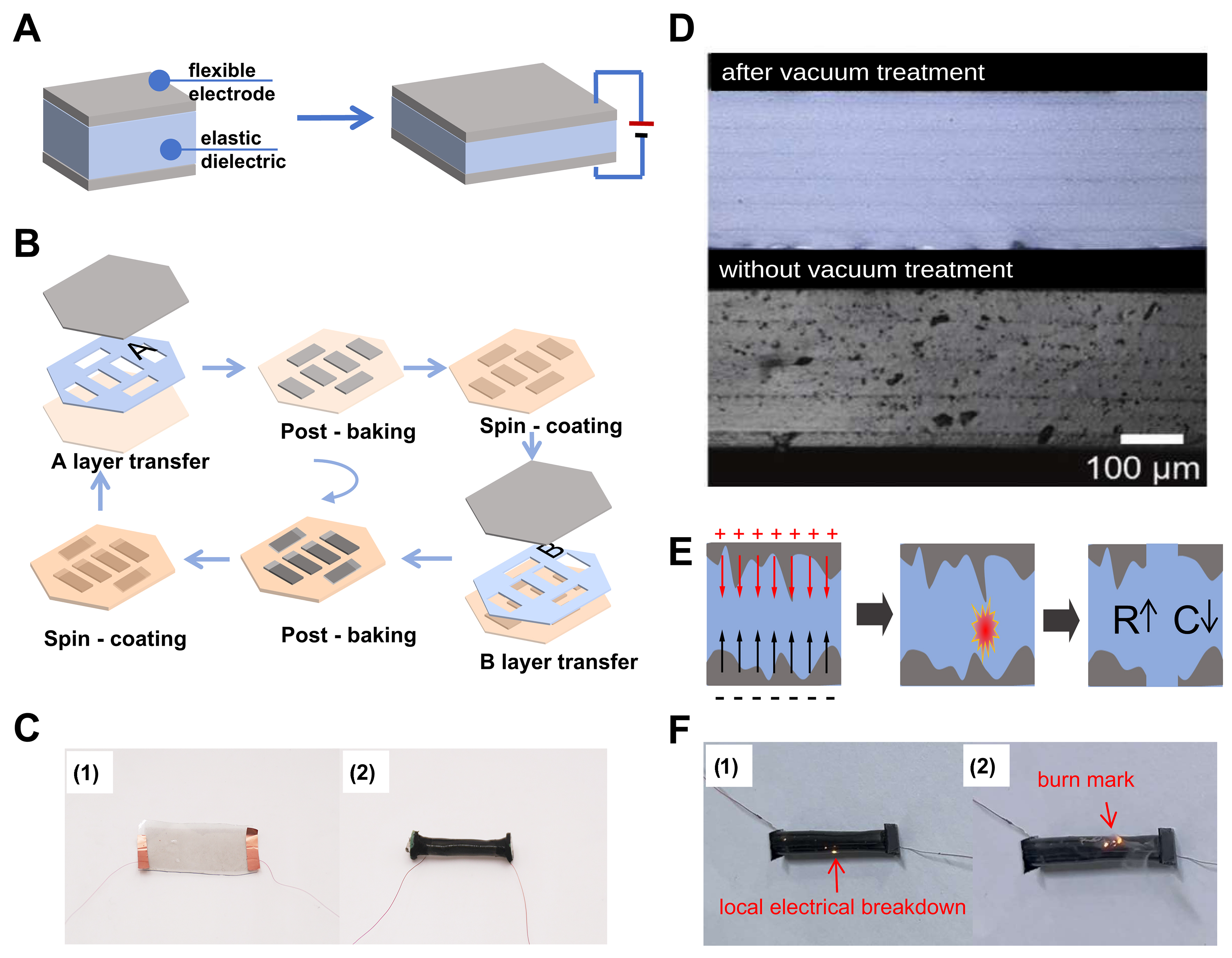
Figure 2. (A) Working principle of the single-layer DEA; (B) Schematic diagram of the DEAs device fabrication process; (C) Schematic diagram of the planar-type DEAs (1) and rolled-type DEAs (2); (D) Comparative images of DEAs cross-sections prior to vacuuming (lower figure) and subsequent to vacuuming (upper figure); (E) Schematic diagram of the self-cleaning process; (F) Local electrical breakdown and burn marks of the DEAs device. Photograph taken by the authors (Figure 2C and F). DEA: Dielectric elastomer actuator.
Self-cleaning
During the fabrication of the DEAs, bubbles may be occasionally introduced into the elastomer, rendering the elastomer more susceptible to breakdown under high voltage. Typically, vacuum treatment can remove most of the visible bubbles, as depicted in Figure 2D. Nevertheless, small bubbles with a diameter of less than 3 μm still persist. Additionally, issues such as uneven distribution and agglomeration of SWCNTs in the electrode layer are likely to arise during suction filtration or electrode transfer printing. Both of these factors will increase the breakdown risk of the DEAs. To further mitigate the impact of these defects on performance, this study incorporates a self-cleaning process: prior to actual operation, a high voltage was first applied to both sides of the DEAs, thereby forming a strong electric field near the defects and causing local breakdown[44]. Due to the property of SWCNTs to degrade and vaporize at high temperatures, this process can eliminate microscopic defects without resulting in permanent failure of the actuator [Figure 2E].
During our experiments, the direct current (DC) drive voltage was incremented from 0 to 1,000 V at a rate of 50 V every 10 s to perform the self-cleaning process on the device. As depicted in Figure 2F (1) small sparks within the DEAs can be directly witnessed under high voltages exceeding 500 V. These sparks are attributed to local electrical breakdowns at defects. To eradicate all defects within the working range, the self-cleaning process can be reiterated on the DEAs. After multiple self-cleaning treatments, it can be observed that the sparks gradually diminish, indicating the successful elimination of defects. It is important to note that during the self-cleaning process, the voltage employed should be increased gradually to avoid exceeding the limit, which may result in the deterioration of device performance or even burnout, as shown in Figure 2F (2).
RESULTS AND DISCUSSION
Bending performance of the DEAs
For the purpose of evaluating the bending performance, one end of the DEAs was fixed. Subsequently, the maximum bending angles produced at the free end of the DEAs were measured at different frequencies, both in air and in water, under a 500 V sinusoidal driving voltage. As can be seen from Figure 3A, in air, both the planar-type DEAs and the rolled-type DEAs exhibit the maximum bending angle response around 8 Hz. Moreover, the former demonstrates a greater bending capacity than the latter. However, when both devices were operating in water, the situation was reversed. The planar-type DEAs had very poor bending capacity underwater: the high-resistance environment in water significantly weakened the driving ability of the actuator. Conversely, the rolled-type DEAs still had a certain degree of bending capacity within the bandwidth range below 15 Hz, and the amplitude reached its maximum at 12 Hz[45]. The details of the experimental setup for measuring the bending angles of the two configurations of DEAs in air and water media are presented in Supplementary Note 2.
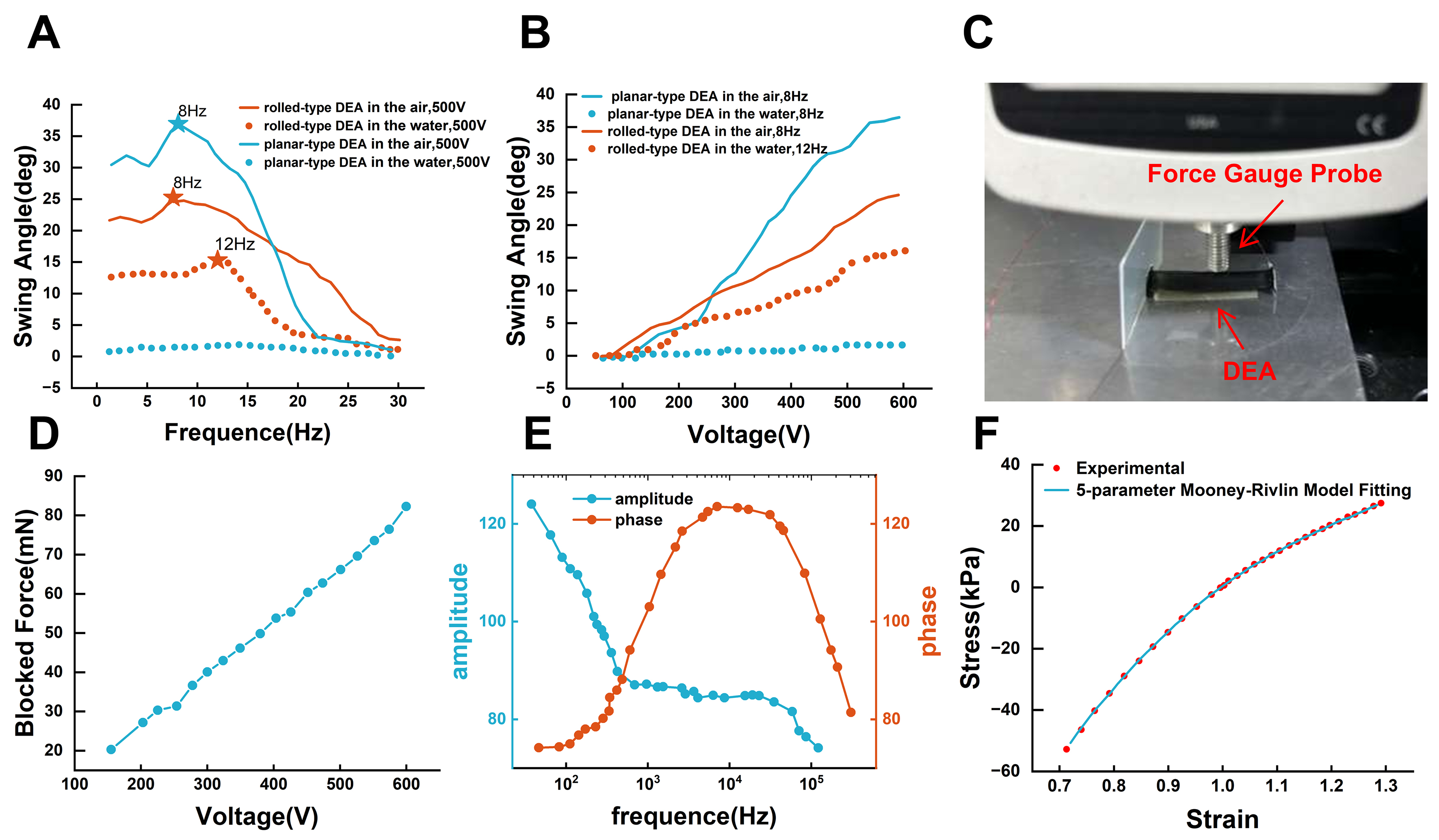
Figure 3. (A) Bending performances of the planar-type DEAs and the rolled-type DEAs of different driving frequencies in air and underwater; the stars in the figure represent the optimal work frequency for different conditions; (B) Bending performances of the planar-type DEAs and the rolled-type DEAs under optimal frequencies with different voltages; (C) Force measurement for the rolled-type DEAs; (D) Variation of output force under different driving voltage for the rolled-type DEAs; (E) Amplitude and phase response curve of DEAs under frequency sweeping test; (F) The experimental results of stress-strain behavior and fitting results using Mooney-Rivlin model with 5 parameters. Photograph taken by the authors (Figure 3C). DEAs: Dielectric elastomer actuators.
At the optimal working frequencies of 8 Hz in air and 12 Hz in water, a sinusoidal voltage within the range of 100 to 600 V was further applied across the tested actuator to measure the bending angle of the free end. The test results are presented in Figure 3B. In air, the maximum swing amplitudes of the planar-type DEAs and the rolled-type DEAs were comparable. Nevertheless, in the underwater experiment, the swing amplitude of the rolled-type DEAs was notably larger. This indicates that winding the DEAs into a cylindrical configuration can enhance the underwater output performance of the DEAs substantially by increasing the cross-sectional area and bending stiffness. It is important to note that during the experiment, when the driving voltage exceeded 600 V, despite the device remaining intact, buckling occurred in the middle section, leading to a decrease in the bending performance.
Subsequently, an output force measurement was carried out on the rolled-type DEAs. The DEAs was fixed perpendicular to the probe of a force gauge. As depicted in Figure 3C, the probe was made to closely fit the bending side of the free end of the DEAs. When actuated by an external voltage, the DEAs tended to bend and deform; however, this bending was obstructed by the probe. The blocked force was employed to characterize the static output force generated by the DEAs. As shown in Figure 3D, this static output force exhibits a strong linear relationship with the voltage, reaching 80 mN at a driving voltage of 600 V.
Electrical and mechanical model of the DEAs
Rolled-type DEAs are generally modeled using a first-order RC circuit[46-48], with equivalent capacitance estimable via the parallel plate capacitor formula[42,49-51]. However, practical experiments using a test circuit as indicated in Supplementary Figure 4 produced results of different model parameters at various frequencies [Supplementary Table 3]. To effectively capture the measured frequency-dependent response, a parasitic capacitance was incorporated (asshown in Supplementary Table 4), and the DEAs were modeled using a second-order lumped RC model for parameter fitting (the test circuit is presented in Supplementary Figure 5). The Bode plot of the frequency range from 0.01 to 100 kHz is presented in Figure 3E. The transfer function of the circuit was derived in Supplementary Note 3, and the electrical parameters [Supplementary Table 5] of the DEAs were obtained through parameter fitting.
Regarding the mechanical properties of DEAs, the Mooney-Rivlin model[52] with five parameters was employed to fit the stress-strain behavior of the DE, as depicted in Figure 3F. The nonlinear least squares problem was resolved using the Levenberg-Marquardt method. The fitting parameters are presented in Supplementary Note 4.
Electromechanical coupling model of the DEAs
To precisely control the overall motion of the actuator, it is crucial to quantitatively analyze the bending motion of the DEAs corresponding to the driving voltage. Thus, an electromechanical coupling model needs to be established. We initiated the derivation using a planar sandwich structure as shown in Figure 4A. The upper and lower layers consist of two planar-type DEAs, and the middle layer is the neutral surface formed by the PET constraint layer, whose stretch can be ignored. When one side of the DEAs is activated (assumed here, for simplicity, to be the upper layer) and strain along the Y-direction is constrained, the resulting stretch in the X-direction induces bending deformation in the Z-direction. The stress in the activated single DEA layer can be modeled using a parallel-plate capacitor representation as[46]
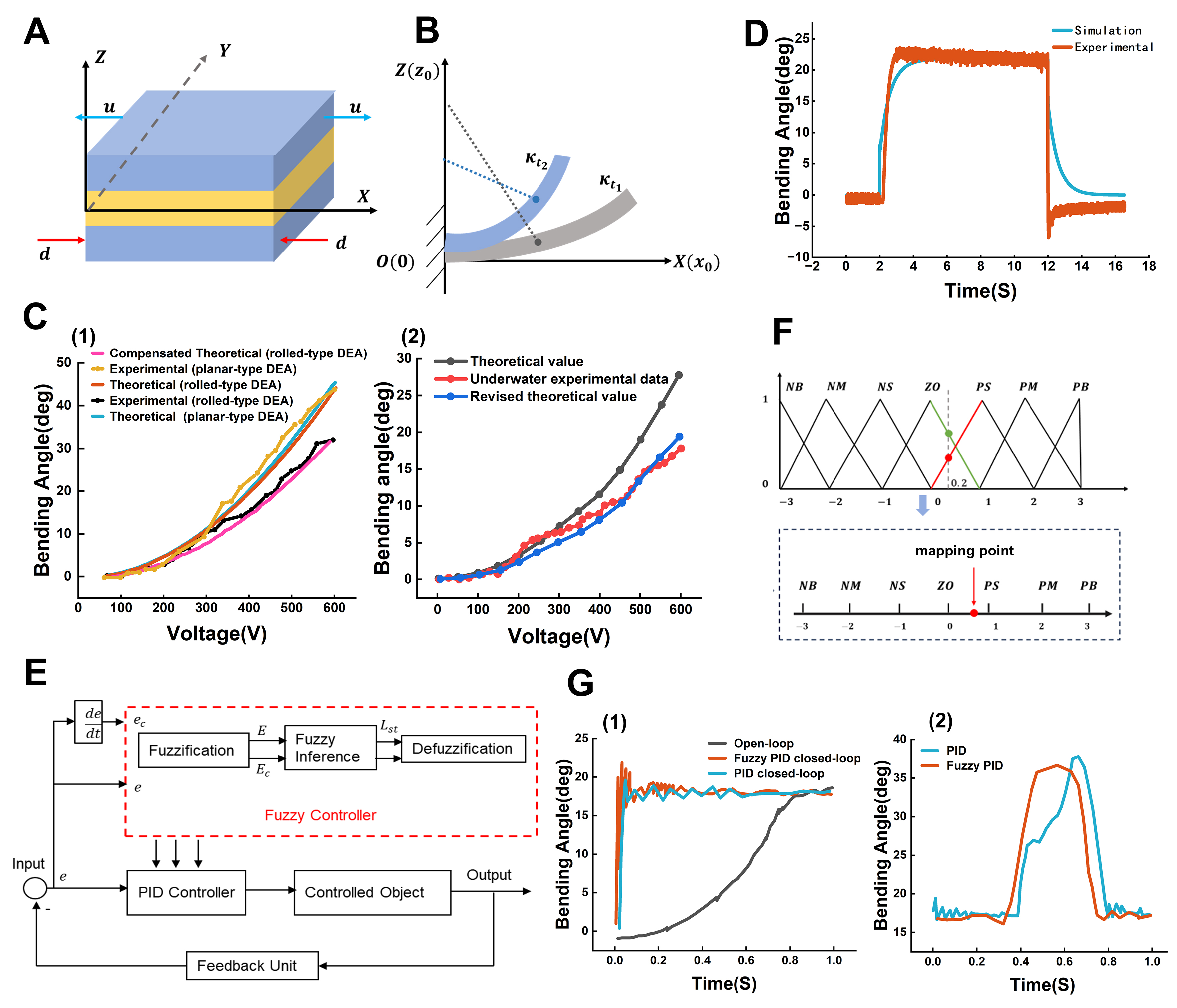
Figure 4. (A) Schematic diagram of sandwich structure of DEAs; (B) Schematic diagram of bending deformation under the constant curvature assumption; (C1) Comparison of theoretical and experimental results for planar and rolled DEAs in air. (C2) Comparison of theoretical and experimental results for rolled-type DEAs underwater; (D) Comparison of the step response of the Simulink simulation and experiment results of rolled-type DEAs underwater; (E) Schematic diagram of control system; (F) Schematic diagram of fuzzy PID control rule; (G1) Comparison of the performances among open-loop control, classical PID control, and fuzzy PID control. (G2) Comparison of responses between PID and fuzzy PID under disturbance. DEAs: Dielectric elastomer actuators; PID: proportional-integral-derivative; NB: Negative Big; NM: Negative Medium; NS: Negative Small; ZO: Zero; PS: Positive Small; PM: Positive Medium; PB: Positive Big.
in which CD is the equivalent capacitance, V is the applied voltage, h is the thickness of the single DEA layer, L and W are the length and width of the planar device respectively; further assuming the thickness of the total device and the constraint layer as H, Hm respectively. The total moment applied to the cross-section of the component is[53],
To simplify the complex nonlinear behavior of the bending motion, we adopted the time-dependent assumption for the bending curvature[39]. Specifically, the actuator’s deformation trajectory is assumed to be a smooth and continuous curve with a uniform curvature, and the curvature only varies with time [Figure 4B]. At any given time, the actuator bends to a specific curvature κ(t). This model is intended to capture the dominant electromechanical bending trend for control design, but it does not explicitly account for spatially non-uniform curvature, viscoelastic hysteresis, rolling-induced geometric non-idealities, or fluid-related nonlinearities. Based on the above assumptions, we define an equivalent bending modulus as follows[35] [Supplementary Note 5]:
where C10, C01, C20, C02, C11 are fitting parameters in the Mooney-Rivlin model. Furthermore, the total area moments of inertia I and the area moments of inertia of the constraint layer Ic can be calculated as[21],
Thus, the internal elastic moment can be described as[51],
and Ec is the Young’s modulus of the constraint layer.
Considering the static condition first, the device should be in force balance: the moment M is equal to the internal elastic moment Mi; thus, the relationship between the applied voltage and the curvature is given by[39]:
This closed-form relationship is used as a control-oriented approximation and is later calibrated/compensated against experiments for rolled and underwater cases.
To validate the electromechanical coupling model, the theoretical curve derived from Equation (6) was compared with experimental bending angle test results. As shown in Figure 4C (1), for the planar-type bending actuator tested in air, the relative error between the theoretical and measured values remains within 10%. In contrast, for the rolled-type DEAs in air, the theoretical error is slightly higher than that of the planar configuration, owing to model simplifications. To mitigate this discrepancy, a scaling factor was introduced. With the scaling parameter set to 0.75, the compensated model error in the current study is reduced to below 10%. This factor arises from the difference in bending efficiency when transforming the DEAs from an ideal planar structure into a cylindrical rolled configuration (see Supplementary Note 6 for details)[54].
Given that the rolled-type DEAs operate in an underwater environment, we further investigate whether the proposed static electromechanical bending model remains applicable under underwater quasi-static conditions. Since the underwater static bending is governed by the same moment-balance structure as in air, a single multiplicative correction factor ηuw is introduced to account for the overall underwater-induced gain shift. As shown in Figure 4C (2), the corrected underwater static predictions agree well with the experimental measurements, and the relative error remains below 10% over the tested voltage range. Details of the correction-factor identification are provided in Supplementary Note 7.
The dynamic model of the actuator operating in water can be further derived as follows: under a driving voltage, the actuator generates an active moment M, which overcomes both the internal elastic moment Mi of the device and the fluid resistance in the aqueous environment, resulting in angular acceleration. Accordingly, the dynamic equation governing the swing motion of the DEAs is established as[53]:
in which D is the damping coefficient underwater, and J denotes the effective total moment of inertia in water, including the actuator inertia and the fluidic contribution.
Combined with Equation (2) and (5) and taking Laplace Transform, the transfer function of the open-loop system for DEAs working underwater is[55]:
Based on Equation (8), a Simulink model was built to simulate the underwater open-loop step response of the rolled-type DEAs, with V2(t) used as the input. The simulated results agree well with experiments [Figure 4D]. The detailed derivation and Simulink implementation are provided in Supplementary Note 8.
Classical PID controllers generally provide stable control performance. However, due to the simplifications in the DEAs model, the variations in the fabrication processes, and the complexity of the hydrodynamic conditions, the dynamic behavior of the actuator and the parameters of the control model may change over time. As the conventional PID controller lacks the ability to adapt its parameters in real time, a fuzzy control strategy was implemented[55-58].
As illustrated in Figure 4E, the fuzzy PID controller primarily comprises three stages: fuzzification of input and output variables, formulation of fuzzy rules, and defuzzification. In the DEAs swing control system implemented in this work, the real-time swing angle of the actuator was measured using a strain sensor. Based on this measurement, the deviation e between the current swing angle and the target value, as well as the deviation change rate ec, were calculated. These two parameters are then fuzzified, whereby the input values are mapped to specific intervals and their degrees of membership are quantified. The fuzzy sets NB, NM, NS, ZE, PS, PM, and PB (representing Negative Big, Negative Medium, Negative Small, Zero, Positive Small, Positive Medium, and Positive Big, respectively) are employed to quantify both the input and output variables. This process was implemented using a linear triangular membership function [Figure 4F]. The fuzzy rules for Kd, Ki and Kp are provided in Supplementary Note 9. During the defuzzification stage, the center-of-gravity method was employed to quantify each output variable and derive a precise output value, as expressed by the following formula[56,58]:
in which zi represents the fuzzy value, z0 is the defuzzified accurate value, and μc(zi) denotes the membership degree of zi. The resulting values of Kd, Ki, and Kp are then applied to the PID controller to achieve fuzzy PID control.
An experimental platform was established to validate the performance of the control system, as illustrated in Figure 4G. In all experiments, the target bending angle was set to 20°. The open-loop controller produced a
To evaluate the anti-interference ability of the closed-loop system, we supplemented the quantitative disturbance test data using an experimental setup identical to that employed in the bending characteristic measurement. Under steady-state conditions, water flow disturbances were introduced through a nozzle, and the angular variation of the actuator was recorded. As shown in Figure 4G, under open-loop control, the actuator required approximately 0.9 s to reach the 18° target angle due to significant underwater damping, which constrained the overall response speed. In contrast, PID closed-loop control shortened the response time to 0.2 s and markedly improved the response speed. When subjected to disturbances corresponding to twice the nominal angle, the actuator regained stable operation within 0.2 s under both PID and fuzzy PID control, indicating robust disturbance-rejection capability of the closed-loop system. Furthermore, compared with conventional PID control, fuzzy PID achieved a further improved response speed and an approximate 20% reduction in overshoot[59].
Applied the controllable DEAs on the centimeter-scale underwater robot
Based on the swing model of the DEAs actuator and the closed-loop control system, a manta-ray-inspired flexible robotic fish was designed and fabricated. This robotic fish is capable of controllable straight-line swimming, turning, and ascending motions in an underwater environment. The caudal-fin-equipped robotic fish consists of three main components: a central body, flexible pectoral fins on both sides, and a caudal fin [Figure 1 (4)]. Each fin is actuated by the rolled-type bending DEAs. The prototype measures 3 cm in body length and 4.5 cm in width. Prior to the swimming performance tests, an underwater endurance test was conducted on the entire robotic fish to test its insulation performance. The key manufacturing steps of the robotic fish, along with the underwater durability tests and their results, are detailed in Supplementary Note 10.
In the straight-swimming experiment, a sinusoidal voltage of 12 Hz ranging from 100 to 600 V was applied to the two actuators of the pectoral fins. Figure 5A (1) and (2) illustrates the robot fish swimming straight under 500 and 300 V respectively, while Figure 5B presents the experimental results across the full voltage range. The data reveal an approximately linear relationship between straight-swimming speed and applied voltage from 200 to 500 V, with a maximum speed of 1.25 body lengths (BL) per second[60]. Beyond 500 V, the swimming speed exhibits a saturation tendency, attributed to buckling of the DEAs and deformation in the flapping motion of the flexible fins. More importantly, when the driving voltage is relatively high, motion path deviation may occur due to inconsistencies in the bilateral actuator fabrication process and external environmental interference [Figure 5A (1) and Supplementary Video Demo 1]. Nevertheless, with closed-loop control, the robotic fish is able to approximately correct its trajectory and maintain an approximately linear motion.
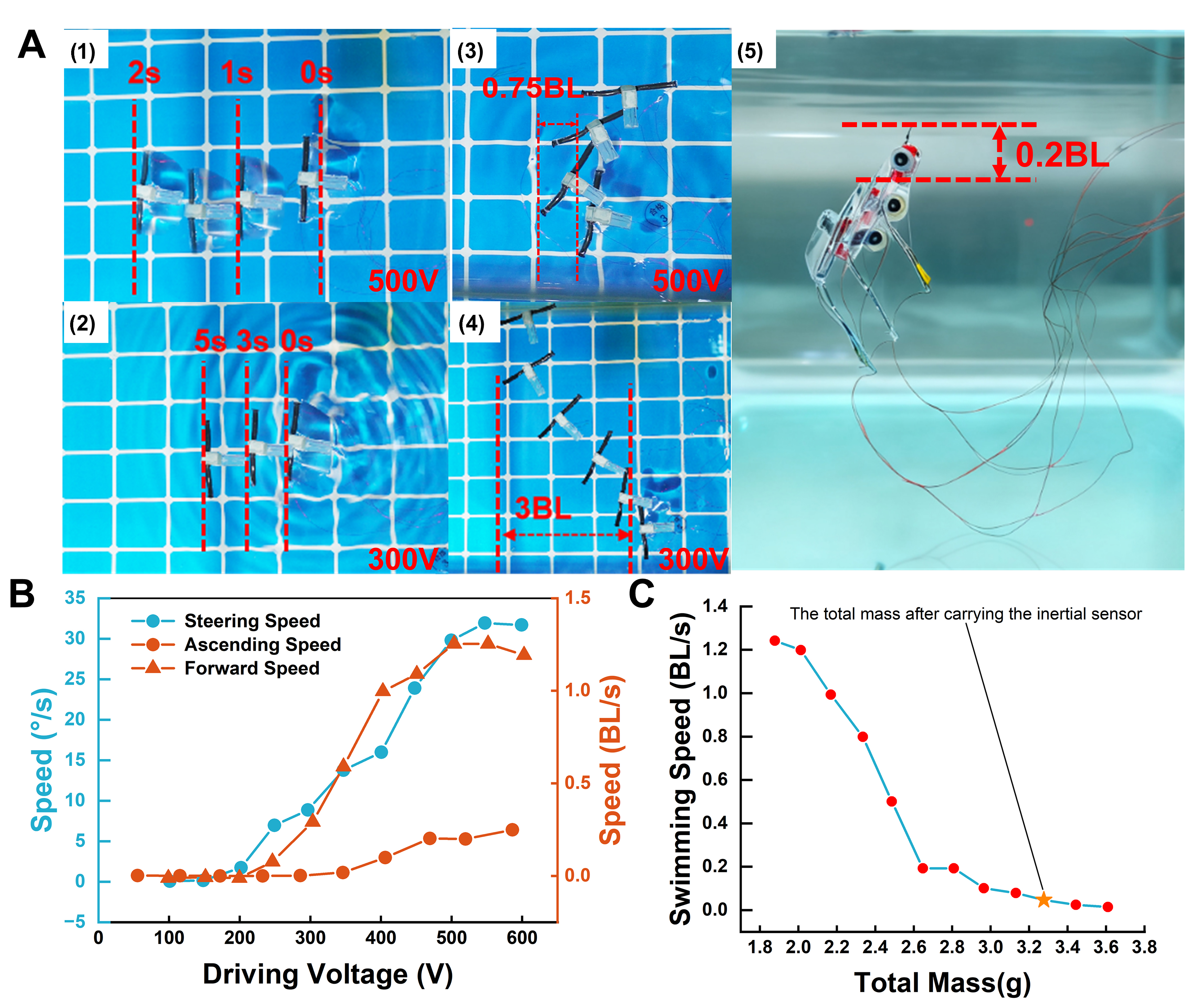
Figure 5. (A) Pictures of robotic fish during straight swimming, turning, and ascending under different voltages; (B) Performances of the robotic fish with different voltage; (C) Results of load experiment. Figure 5A was generated by superimposing the positions of the robotic fish at different time points based on video taken by the authors. BL: Body lengths.
In the turning experiment, the initial heading was set to 0° and the target heading to 90°. One pectoral fin was held stationary, while a 12 Hz sinusoidal voltage ranging from 100 to 600 V was applied solely to the actuator on the opposite pectoral fin. As illustrated in Figure 5A (3) (also see Supplementary Video Demo 2), the robotic fish achieved the target heading within 3 s under a 500 V input, with a yaw rate of approximately 30°/s and a maximum forward displacement of only 0.75 BL during the maneuver. The turning radius was effectively controlled by varying the applied voltage. Figure 5A (4) depicts the turning behavior at 300 V, and the full-range experimental results are summarized in Figure 5B.
In the ascent experiment, the robotic fish was first ballasted to achieve neutral buoyancy, allowing it to remain stationary in water. The caudal fin was then deflected by 40° using a high-voltage DC signal, while a 12 Hz sinusoidal voltage ranging from 100 to 600 V was applied to the bilateral pectoral fin actuators. The ascent behavior at 500 V is illustrated in Figure 5A (5), with the full voltage range results presented in Figure 5B. It was observed that ascending motion requires higher voltages, initiating ascent only above 400 V, and yields a slower velocity compared to straight-line swimming. A load experiment was subsequently performed by incrementally increasing the robotic fish’s payload, and the corresponding swimming speeds under various loads were recorded. As shown in Figure 5C, the swimming speed decreased markedly when the load exceeded 2.6 g. This trend also indicates a diminished motion-stability margin under higher payloads. This is because the elevated propulsion requirement results in a smaller effective actuation margin for rejecting disturbances and sustaining stable swimming. For more detailed discussion between voltage and lift force, see Supplementary Note 11. These findings related to ascent performance and load capacity suggest that despite the actuator motions being precisely controllable, the overall output performance of the actuators still requires improvement.
As depicted by the pentagram in Figure 5C, the weight of the pose sensor is indicated. Thus, when the robotic fish is equipped with the pose sensor, it is unable to swim efficiently. As a result, this study has not yet attained a second-order closed loop capable of autonomously adjusting the swimming posture, which represents a direction for future work.
Discussion and outlook
When the payload exceeds 2.6 g, the swimming speed decreases markedly [Figure 5C], indicating that the increased load leads to a rapid rise in the required propulsion torque, while the present DEAs provides insufficient effective output margin. As a result, the robot becomes more sensitive to disturbances and actuation asymmetry under high-payload conditions, which degrades motion stability, especially near the payload limit. When the driving voltage exceeds 500 V, the speed exhibits a tendency towards saturation [Figure 5B]. This implies that in the high-voltage range, buckling of DEAs and degradation of the flapping kinematics of the flexible fin may take place, thus impeding the linear conversion of further voltage increments into effective thrust gains. In addition, the experimental validation in this work relies primarily on an external high-voltage actuation platform; therefore, endurance time and the onboard energy-supply scheme have not yet been evaluated or discussed under a fully self-contained (untethered) configuration.
Future work will address these limitations along three directions: (i) enhancing the effective DEAs output and propulsion efficiency to extend the high-payload operating range; (ii) mitigate high-voltage buckling instability and fin-kinematic distortion to expand the effective work regime under elevated voltages; and (iii) develop a compact and efficient onboard high-voltage driver module featuring robust waterproof insulation packaging to progress the system from tethered demonstrations to truly autonomous underwater operation.
CONCLUSIONS
In conclusion, to support accurate characterization and robust closed-loop operation of rolled-type DEAs in high-damping underwater environments, this study implements an experimentally validated modeling-to-control pipeline and integrates it into a centimeter-scale manta-ray-inspired robot for underwater verification.
We implement an experimentally calibrated electromechanical model by combining a second-order lumped RC electrical representation (including parasitic capacitance) with and empirical modified mechanical model to derive the transfer function of the DEAs device. A fuzzy-tuned PID closed-loop controller is implemented according to the identified input-output behavior. The system can regain stability within 0.2 s under disturbances equivalent to twice the nominal angle. Moreover, the overshoot is decreased by approximately 20% compared with traditional PID control. This further enhances the anti-interference performance of the DEAs in comparison with open-loop control and traditional PID control.
The integrated “fabrication-modeling-control” framework is successfully applied to a 3 cm-long manta-ray-inspired soft robot, which demonstrates competitive maneuverability for centimeter-scale underwater robots. Overall, the proposed workflow offers a practical approach for centimeter-scale DEAs driven underwater robots, and it can be extended to other soft robotic systems through appropriate identification and tuning.
DECLARATIONS
Authors’ contributions
Performed the experiments, interpreted the data and wrote the paper: Zhang, Y.
Designed the model and the control system, performed the experiments: Zhang, C. (Chen Zhang)
Designed the prototypes and the fabrication processes, performed the experiments: Zhang, C. (Chenyu Zhang)
Assisted the experiments: Shi, J.
Directed the research and revised the paper: Qu, J.; Qian, X.
Availability of data and materials
All data needed to evaluate the conclusions are available in the manuscript and the Supplementary Materials.
AI and AI-assisted tools statement
Not applicable.
Financial support and sponsorship
This work is supported by the National Natural Science Foundation of China (Grant No. 52571385), the Shenzhen Science and Technology Program (Grant No. JCYJ20240813112107010) and Tsinghua SIGS Cross-Disciplinary Research and Innovation Fund (Grant No. 2022002).
Conflicts of interest
All authors declared that there are no conflicts of interest.
Ethical approval and consent to participate
Not applicable.
Consent for publication
Not applicable.
Copyright
© The Author(s) 2026.
Supplementary Materials
REFERENCES
1. Qu, J.; Xu, Y.; Li, Z.; et al. Recent advances on underwater soft robots. Adv. Intell. Syst. 2024, 6, 2300299.
2. Yan, S.; Wu, Z.; Wang, J.; et al. Recent advances in design, sensing, and autonomy of biomimetic robotic fish: a review. IEEE/ASME. Trans. Mechatron. 2025, 30, 3517-36.
3. Li, Y.; Xu, Y.; Wu, Z.; et al. A comprehensive review on fish-inspired robots. Int. J. Adv. Robot. Syst. 2022, 19, 17298806221103707.
4. Cui, Z.; Li, L.; Wang, Y.; Zhong, Z.; Li, J. Review of research and control technology of underwater bionic robots. Intell. Mar. Technol. Syst. 2023, 1, 10.
5. Zhu, J.; White, C.; Wainwright, D. K.; Di Santo, V.; Lauder, G. V.; Bart-Smith, H. Tuna robotics: a high-frequency experimental platform exploring the performance space of swimming fishes. Sci. Robot. 2019, 4, eaax4615.
6. Ding, F.; Wang, R.; Zhang, T.; Zheng, G.; Wu, Z.; Wang, S. Real-time trajectory planning and tracking control of bionic underwater robot in dynamic environment. Cyborg. Bionic. Syst. 2024, 5, 0112.
7. Iguchi, K.; Shimooka, T.; Uchikai, S.; et al. Agile robotic fish based on direct drive of continuum body. npj. Robot. 2024, 2, 14.
8. Li, G.; Shen, P.; Wong, T. W.; et al. Plasticized electrohydraulic robot autopilots in the deep sea. Sci. Robot. 2025, 10, eadt8054.
9. Marchese, A. D.; Onal, C. D.; Rus, D. Autonomous soft robotic fish capable of escape maneuvers using fluidic elastomer actuators. Soft. Robot. 2014, 1, 75-87.
10. Xiong, J.; Chen, J.; Lee, P. S. Functional fibers and fabrics for soft robotics, wearables, and human-robot interface. Adv. Mater. 2021, 33, e2002640.
11. Guo, Y.; Liu, L.; Liu, Y.; Leng, J. Review of dielectric elastomer actuators and their applications in soft robots. Adv. Intell. Syst. 2021, 3, 2000282.
12. Morimoto, Y.; Onoe, H.; Takeuchi, S. Biohybrid robot powered by an antagonistic pair of skeletal muscle tissues. Sci. Robot. 2018, 3, eaat4440.
13. Zhang, Y.; Zhang, N.; Hingorani, H.; et al. Fast-response, stiffness-tunable soft actuator by hybrid multimaterial 3D printing. Adv. Funct. Mater. 2019, 29, 1806698.
14. Hu, W.; Lum, G. Z.; Mastrangeli, M.; Sitti, M. Small-scale soft-bodied robot with multimodal locomotion. Nature 2018, 554, 81-5.
15. Gu, G.; Zhang, N.; Xu, H.; et al. A soft neuroprosthetic hand providing simultaneous myoelectric control and tactile feedback. Nat. Biomed. Eng. 2023, 7, 589-98.
16. Lussi, J.; Mattmann, M.; Sevim, S.; et al. A submillimeter continuous variable stiffness catheter for compliance control (Adv. Sci. 18/2021). Adv. Sci. 2021, 8, 2170118.
17. Katzschmann, R. K.; DelPreto, J.; MacCurdy, R.; Rus, D. Exploration of underwater life with an acoustically controlled soft robotic fish. Sci. Robot. 2018, 3, eaar3449.
18. Won, P.; Kim, K. K.; Kim, H.; et al. Transparent soft actuators/sensors and camouflage skins for imperceptible soft robotics. Adv. Mater. 2021, 33, e2002397.
19. Li, G.; Chen, X.; Zhou, F.; et al. Self-powered soft robot in the Mariana Trench. Nature 2021, 591, 66-71.
20. Wang, Y.; Wang, Y.; Mushtaq, R. T.; Wei, Q. Advancements in soft robotics: a comprehensive review on actuation methods, materials, and applications. Polymers 2024, 16, 1087.
21. Youn, J.; Jeong, S. M.; Hwang, G.; et al. Dielectric elastomer actuator for soft robotics applications and challenges. Appl. Sci. 2020, 10, 640.
23. Chen, Z.; Um, T. I.; Bart-Smith, H. A novel fabrication of ionic polymer–metal composite membrane actuator capable of 3-dimensional kinematic motions. Sens. Actuators. A. Phys. 2011, 168, 131-9.
24. Hubbard, J. J.; Fleming, M.; Palmre, V.; Pugal, D.; Kim, K. J.; Leang, K. K. Monolithic IPMC fins for propulsion and maneuvering in bioinspired underwater robotics. IEEE. J. Ocean. Eng. 2014, 39, 540-51.
25. Chen, Z. A review on robotic fish enabled by ionic polymer-metal composite artificial muscles. Robotics. Biomim. 2017, 4, 24.
26. Zhang, C. Fluid-structure interaction analysis of a bionic robotic fish based on a macrofiber composite material. Biomimetics 2025, 10, 393.
27. Wang, Z.; Hang, G.; Li, J.; Wang, Y.; Xiao, K. A micro-robot fish with embedded SMA wire actuated flexible biomimetic fin. Sens. Actuators. A. Phys. 2008, 144, 354-60.
28. Wang, Z.; Wang, Y.; Li, J.; Hang, G. A micro biomimetic manta ray robot fish actuated by SMA. In 2009 IEEE International Conference on Robotics and Biomimetics (ROBIO), Guilin, China. Dec 19-23, 2009. IEEE; 2009. pp. 1809-13.
29. Chai, Z.; Gao, W.; Kong, J.; et al. A teleost-inspired multimodal locomotion soft robot with high bandwidth artificial muscles. Soft. Robot. 2026, 13, 218-31.
30. Chen, X.; Ning, K.; Shigemune, H.; Sawada, H. An untethered soft robotic fish using SMA wires and its performance analysis. Int. J. Mechatron. Autom. 2021, 8, 229.
31. Zhao, Q.; Liu, S.; Chen, J.; et al. Fast-moving piezoelectric micro-robotic fish with double caudal fins. Robot. Autonom. Syst. 2021, 140, 103733.
32. Li, T.; Li, G.; Liang, Y.; et al. Fast-moving soft electronic fish. Sci. Adv. 2017, 3, e1602045.
33. Xu, S.; Nunez, C. M.; Souri, M.; Wood, R. J. A compact DEA-based soft peristaltic pump for power and control of fluidic robots. Sci. Robot. 2023, 8, eadd4649.
34. Li, J.; He, J.; wang, Y.; Yu, K.; Wozniak, M.; Wei, W. A biomimetic flexible fishtail embedded with shape memory alloy wires. IEEE. Access. 2019, 7, 166906-16.
35. Zhong, Y.; Xie, X.; Zhu, J.; Wu, K.; Wang, C. Biomimetic crawling robot based on dielectric elastomer: design, modeling and experiment. IEEE. Robot. Autom. Lett. 2024, 9, 9669-76.
36. Gu, J.; Wang, J.; Liu, Z.; Tan, M.; Yu, J.; Wu, Z. Deformation control and thrust analysis of a flexible fishtail with muscle-like actuation. IEEE. Trans. Robot. 2025, 41, 159-79.
37. Li, X.; Rao, D.; Zhang, M.; et al. A jelly-like artificial muscle for an untethered underwater robot. Cell. Rep. Phys. Sci. 2024, 5, 101957.
38. Qing, H.; Guo, J.; Zhu, Y.; et al. Spontaneous snapping-induced jet flows for fast, maneuverable surface and underwater soft flapping swimmer. Sci. Adv. 2024, 10, eadq4222.
39. Shintake, J.; Shea, H.; Floreano, D. Biomimetic underwater robots based on dielectric elastomer actuators. In 2016 IEEE/RSJ International Conference on Intelligent Robots and Systems (IROS), Daejeon, South Korea. Oct 19-14, 2016. IEEE; 2016. pp. 4957-62.
40. Wang, Y.; Tan, J.; Zhao, D. Design and experiment on a biomimetic robotic fish inspired by freshwater stingray. J. Bionic. Eng. 2015, 12, 204-16.
41. Xu, Z.; Liang, J.; Zhou, Y. Manta ray-inspired soft robotic swimmer for high-speed and multi-modal swimming. In 2024 IEEE/RSJ International Conference on Intelligent Robots and Systems (IROS), Abu Dhabi, United Arab Emirates. Oct 14-18, 2024. IEEE; 2024. pp. 235-40.
42. von Szczepanski, J.; Opris, D. M. High-permittivity polysiloxanes for solvent-free fabrication of dielectric elastomer actuators. Adv. Mater. Technol. 2023, 8, 2201372.
43. Sun, Y.; Li, D.; Wu, M.; et al. Origami-inspired folding assembly of dielectric elastomers for programmable soft robots. Microsyst. Nanoeng. 2022, 8, 37.
44. Rizzello, G. A review of cooperative actuator and sensor systems based on dielectric elastomer transducers. Actuators 2023, 12, 46.
45. Li, S.; Gao, Z.; Yang, W.; Wang, R.; Zhang, L. Recent advances in dielectric elastomer actuator-based soft robots: classification, applications, and future perspectives. Gels 2025, 11, 844.
46. Zhao, H.; Hussain, A. M.; Duduta, M.; Vogt, D. M.; Wood, R. J.; Clarke, D. R. Compact dielectric elastomer linear actuators. Adv. Funct. Mater. 2018, 28, 1804328.
47. Ren, Z.; Kim, S.; Ji, X.; et al. A high-lift micro-aerial-robot powered by low-voltage and long-endurance dielectric elastomer actuators. Adv. Mater. 2022, 34, e2106757.
48. Chen, Y.; Xu, S.; Ren, Z.; Chirarattananon, P. Collision resilient insect-scale soft-actuated aerial robots with high agility. IEEE. Trans. Robot. 2021, 37, 1752-64.
49. Chen, Y.; Agostini, L.; Moretti, G.; Fontana, M.; Vertechy, R. Dielectric elastomer materials for large-strain actuation and energy harvesting: a comparison between styrenic rubber, natural rubber and acrylic elastomer. Smart. Mater. Struct. 2019, 28, 114001.
50. Hajiesmaili, E.; Clarke, D. R. Dielectric elastomer actuators. J. Appl. Phys. 2021, 129, 151102.
51. Nagai, T.; Shintake, J. Rolled dielectric elastomer antagonistic actuators for biomimetic underwater robots. Polymers 2022, 14, 4549.
53. Zou, J.; Kassim, S. O.; Ren, J.; Vaziri, V.; Aphale, S. S.; Gu, G. A generalized motion control framework of dielectric elastomer actuators: dynamic modeling, sliding-mode control and experimental evaluation. IEEE. Trans. Robot. 2024, 40, 919-35.
54. Wang, B.; Li, L.; Xu, M.; et al. Adaptive multimodal swimming gaits in a reconfigurable modular soft robotic fish. Sci. Adv. 2026, 12, eaea1299.
55. Huang, P.; Wang, Y.; Wu, J.; Su, C.; Noda, R.; Fukushima, E. F. Modeling and control of dielectric elastomer actuator based on T–S fuzzy model framework and LMI theory. Int. J. Fuzzy. Syst. 2025, 27, 2506-18.
56. Teeter, J. T.; Chow, M.; Brickley, J. J. A novel fuzzy friction compensation approach to improve the performance of a DC motor control system. IEEE. Trans. Ind. Electron. 1996, 43, 113-20.
57. Huang, Y.; Sung, C. C. Function-based controller for linear motor control systems. IEEE. Trans. Ind. Electron. 2010, 57, 1096-105.
58. Liu, X.; Guo, S.; Li, C.; Lei, Q.; Nie, J. Study on a novel fuzzy PID control system for the ellipsoidal underwater robot. In 2024 IEEE International Conference on Mechatronics and Automation (ICMA), Tianjin, China. Aug 04-07, 2024. IEEE; 2024. pp. 1502-7.
59. Liu, X.; Li, J.; Xing, Y.; et al. Soft biomimetic underwater vehicles: a review of actuation mechanisms, structure designs and underwater applications. Micromachines 2026, 17, 258.
Cite This Article
How to Cite
Download Citation
Export Citation File:
Type of Import
Tips on Downloading Citation
Citation Manager File Format
Type of Import
Direct Import: When the Direct Import option is selected (the default state), a dialogue box will give you the option to Save or Open the downloaded citation data. Choosing Open will either launch your citation manager or give you a choice of applications with which to use the metadata. The Save option saves the file locally for later use.
Indirect Import: When the Indirect Import option is selected, the metadata is displayed and may be copied and pasted as needed.
About This Article
Copyright

Data & Comments
Data
0


Comments
Comments must be written in English. Spam, offensive content, impersonation, and private information will not be permitted. If any comment is reported and identified as inappropriate content by OAE staff, the comment will be removed without notice. If you have any queries or need any help, please contact us at support@oaepublish.com.