




fig3
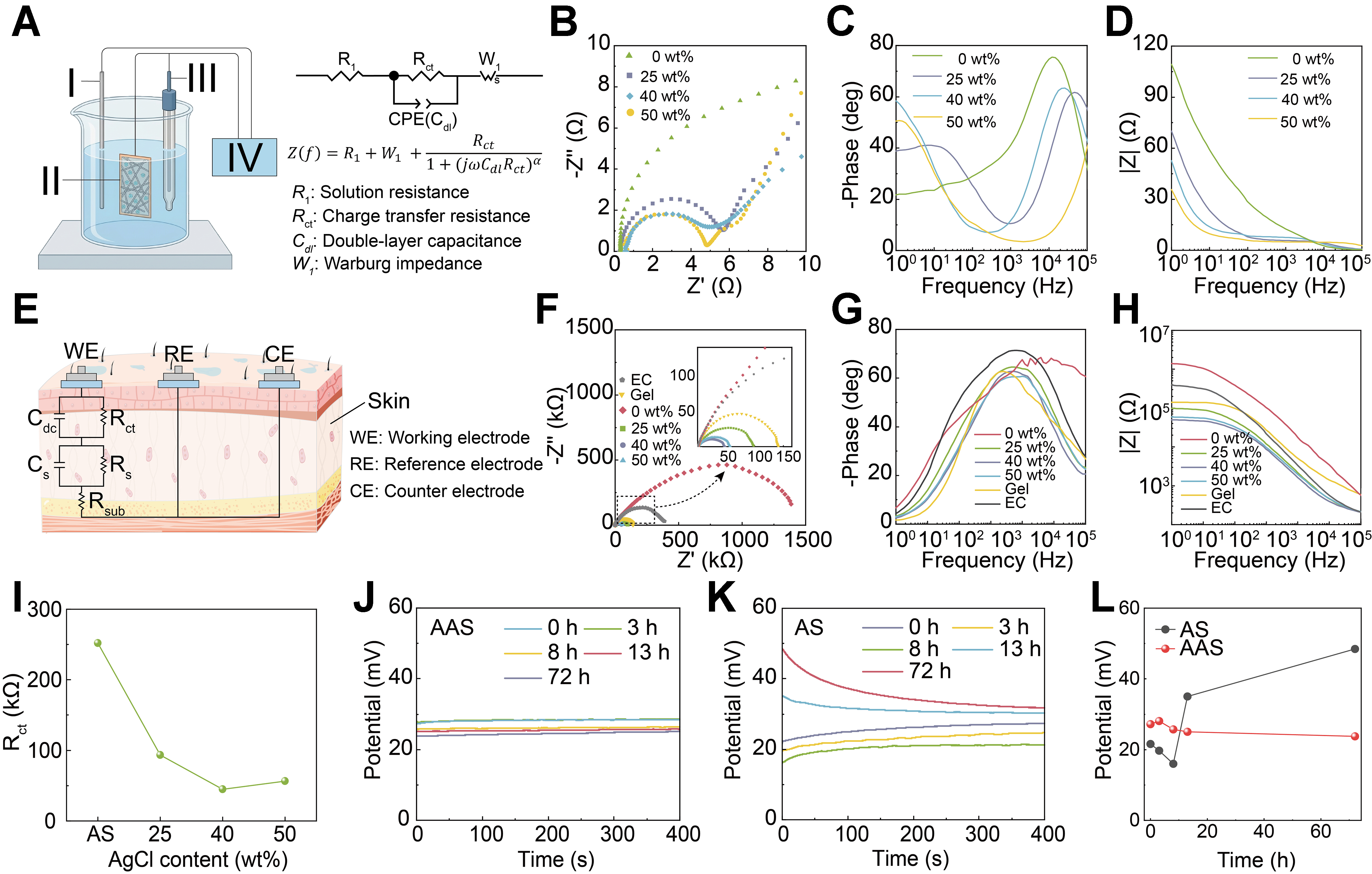
Figure 3. Interfacial electrical properties and stability of the AAS electrode. (A) Schematic illustration of the three-electrode configuration and corresponding equivalent circuit model; (B) Nyquist plots of AS and AAS electrodes with varying AgCl content; Bode plots showing (C) Phase angle and (D) Impedance magnitude as a function of frequency; (E) Schematic illustration of the skin-electrode impedance measurement configuration and the corresponding equivalent circuit model; (F-H) Skin–electrode impedance characteristics: (F) Nyquist plot, and (G and H) Bode plots of phase angle and impedance magnitude; (I) Extracted Rct values obtained from equivalent circuit fitting; (J and K) Open-circuit potential stability of (J) AAS and (K) AS electrodes; (L) Long-term potential drift comparison between AS and AAS electrodes. AAS: AgNWs/AgCl/SEBS [AgNWs: silver nanowires, SEBS: poly(styrene-ethylene-butylene-styrene)]; AS: AgNWs/SEBS; CPE: constant phase element; EC: electrochemically chlorinated.